Multi-sensor distortion mapping method and system

a mapping method and multi-sensor technology, applied in the field of tracking systems, can solve problems such as the magnitude and direction of the field change, the error in the determined location of the device, and the distortion of magnetic fields

Active Publication Date: 2008-04-03
NORTHERN DIGITAL
View PDF20 Cites 91 Cited by
  • Summary
  • Abstract
  • Description
  • Claims
  • Application Information

AI Technical Summary

Problems solved by technology

However, as those of ordinary skill in the art appreciate, the presence of field distorting objects may result in distortions in the magnetic field emitted from the EM transmitters and thereby change the magnitude and direction of this field.
For example, the presence of a signal from another source, the magnetic field of the eddy current in a conductive object, or the field distorting effect of a ferro-magnetic object can result in these distortions.
Unless compensated for, these distortions will result in error in the determined location of the device.
One source of magnetic field distortions may be the equipment utilized in the tracking system itself.
As those of ordinary skill in the art will appreciate, these imaging systems typically include conducting objects (e.g., the C-arm) that result in the above-described field distortions.
This process of collecting thousands of data points is time consuming and resource intensive.
However, the impact of these field distorting objects on the magnetic field in the clinical environment is generally not known, and the field distorting objects are frequently transient.
However, these techniques only detect field distortions in the immediate vicinity of the two sensors and do not convey the extent of field distortions in the larger navigated volume.

Method used


Image

  • Multi-sensor distortion mapping method and system
  • Multi-sensor distortion mapping method and system
  • Multi-sensor distortion mapping method and system

Examples


Embodiment Construction

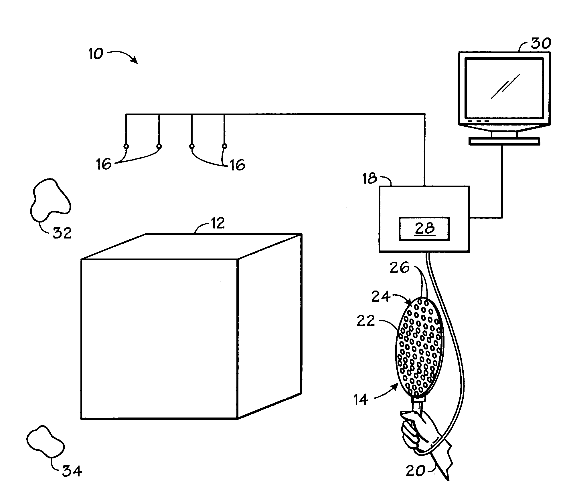
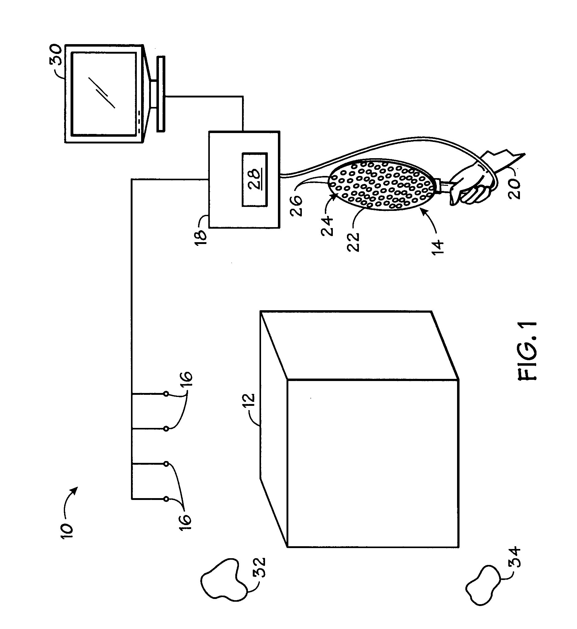
[0021]FIG. 1 illustrates diagrammatically a system 10 for detecting field distortions within a volume of interest 12. As illustrated, the system 10 generally includes an EM sensor assembly 14, a plurality of EM sensors 16, and a tracker 18.

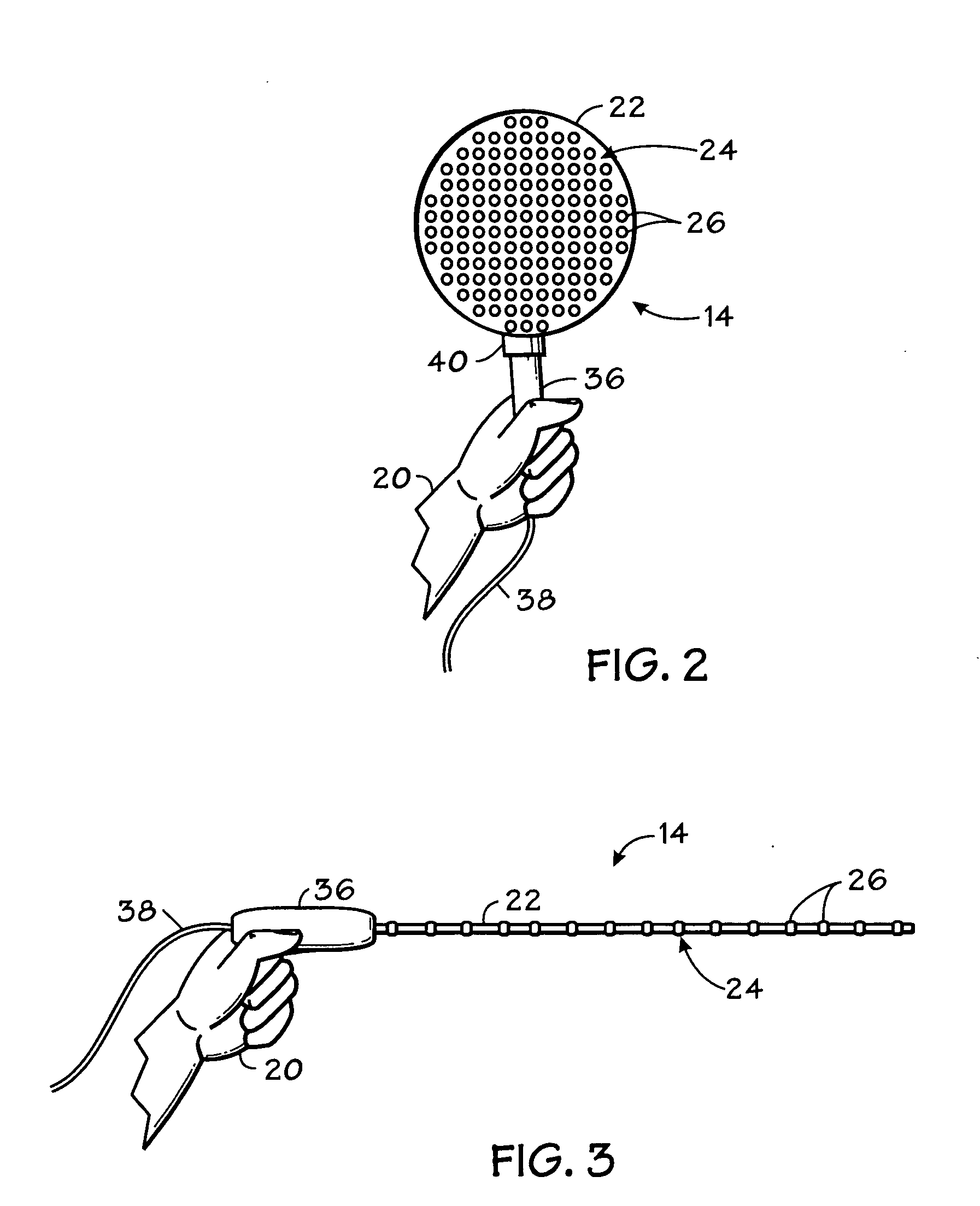
[0022]In the illustrated embodiment, an operator (represented in FIG. 1 by hand 20) employs the EM sensor assembly 14 to detect field distortions within the volume of interest 12. The volume of interest 12 may be any suitable volume where it is desired to determine magnetic field distortions. For example, the volume of interest 12 may be a volume to be navigated by a medical device, wherein a tracking system will be used to determine the location of the medical device in the volume of interest 12. EM sensor assembly 14 comprises a body 22 and an array 24 of EM sensors 26 positioned on a surface of the body 22. In general, the operator 20 moves the EM sensor assembly 14 through the volume of interest 12 so that signals are transmitted from one or m...


PUM


Abstract

In one aspect of the present technique, an array of electromagnetic sensors is positioned within a volume of interest. In the presence of an electromagnetic field, the array of electromagnetic sensors is sampled to acquire signals representative of the location of the electromagnetic sensors in the array. The electromagnetic field distortion within the volume of interest is determined based on the acquired signals. In another aspect of the present technique, a system for detecting electromagnetic field distortions includes an electromagnetic sensor assembly for positioning within a volume of interest, a plurality of electromagnetic sensors for transmitting or receiving signals representative of the location of the electromagnetic sensors on the sensor assembly; and a tracker. In another aspect of the present technique, an electromagnetic sensor assembly for detecting electromagnetic field distortion includes a body, and an array of electromagnetic sensors positioned on the body.

Description

BACKGROUND[0001]The present invention relates generally to tracking systems that use magnetic fields such as for surgical interventions, and other medical procedures. More particularly, the present invention relates to apparatus and techniques for determining magnetic field distortion in such systems.[0002]Tracking systems have been used to provide an operator (e.g., a physician) with information to assist in the precise and rapid positioning of a medical (e.g., surgical) device in a patient's body. In general, an image is displayed for the operator that includes a visualization of the patient's anatomy with an icon or image representing the device superimposed thereon. As the device is positioned with respect to the patient's body, the displayed image is updated to reflect the correct device coordinates. The image of the patient's anatomy may be generated either prior to or during the medical or surgical procedure. Moreover, any suitable medical imaging technique, such as X-ray, co...

Claims


Application Information

Patent Timeline
Patent Type & Authority Applications(United States)
IPC IPC(8): G01B7/30
CPCA61B19/52A61B19/5244A61B2019/5251A61B2019/5238A61B2017/00725A61B6/4441A61B6/487A61B6/582A61B90/36A61B34/20A61B2090/376A61B2034/2051
Inventor JENSEN, VERNON THOMAS
Owner NORTHERN DIGITAL
Why Eureka
Try Eureka