Continuously Variable Transmission with Mutliple Outputs

Active Publication Date: 2008-04-03
HDT EXPEDITIONARY SYST
View PDF11 Cites 117 Cited by
  • Summary
  • Abstract
  • Description
  • Claims
  • Application Information

AI Technical Summary

Benefits of technology

[0007] In accordance with a preferred embodiment of the invention, a transmission or actuator includes an input driving multiple outputs, each output having an independently and continuously variable transmission ratio. This transmission permits a single, powered actuator to be shared for driving multiple outputs, permitting more efficient utilization of power and savings of weight and space without sacrificing the ability to independently control each out

Problems solved by technology

Multiple-degree-of-freedom systems for many applications often require multiple actuators that are oversized in terms of power.
This leads to heavy systems.
Heavy

Method used


Image

  • Continuously Variable Transmission with Mutliple Outputs
  • Continuously Variable Transmission with Mutliple Outputs
  • Continuously Variable Transmission with Mutliple Outputs

Examples


Embodiment Construction

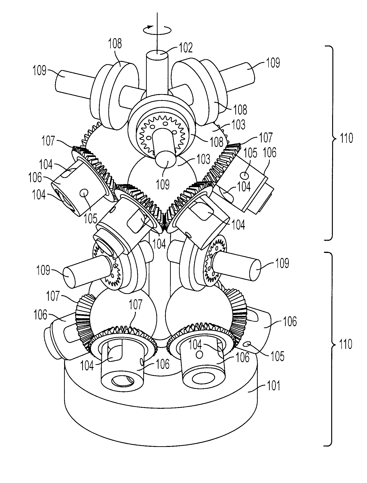
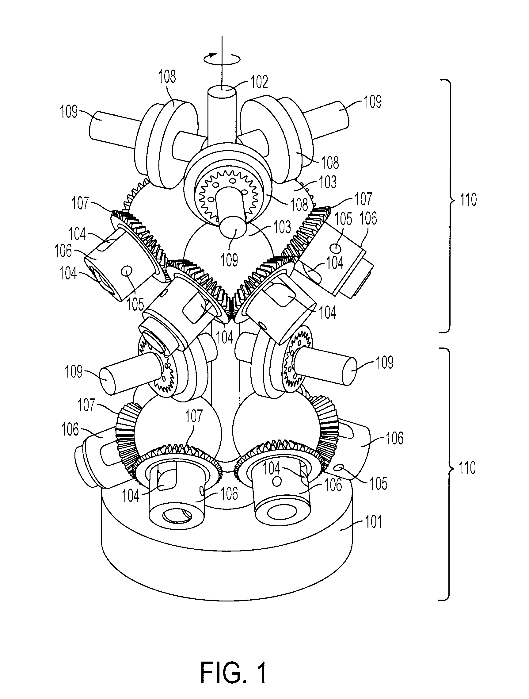
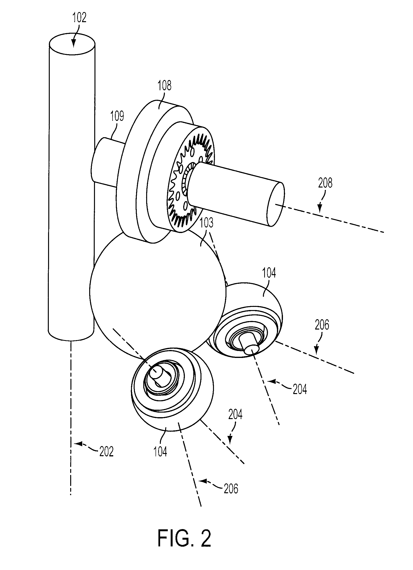
[0013] In the example illustrated in the accompanying figures, and described in detail below, a plurality of continuously variable transmission units (CVTs) are arrayed circumferentially around a common rotating shaft. The shaft is connected to a source of input rotational motion, for example an electric motor. Additional arrays can be distributed along the length of the common shaft. Each CVT enables rapid, accurate and independent adjustment of the transmission ratio of each output by means of a computer. The transmission thus easily permits relating output speeds one to another under computer control, making possible the establishment of virtual surfaces and other haptic effects in a multidimensional workspace to which the transmission outputs are kinematically linked. An example of such a workspace is that of a robotic or prosthetic hand. With continuously variable ratios, each CVT further enables extending the range of capabilities of the input motor beyond the range of speed a...


PUM


Abstract

A transmission or actuator offering multiple rotational outputs proportionate in speed to that of a common rotational input, each output according to its own ratio. The ratios are continuously variable between positive and negative values, including zero, and may be varied by electromechanical actuators under computer control. The transmission relates the output speeds one to another under computer control, and thus makes possible the establishment of virtual surfaces and other haptic effects in a multidimensional workspace to which the transmission outputs are kinematically linked. An example of such a workspace is that of a robotic or prosthetic hand.

Description

[0001] This application claims the benefit of U.S. provisional patent application No. 60 / 841,710, filed Sep. 1, 2006, which is incorporated herein by reference for all purposes.BACKGROUND OF THE INVENTION [0002] Passive robots intended for collaboration with a human operator, which are sometimes called “cobots,” move in response to a force that a user manually applies to its end point. Limits or constraints placed on the end point position determine the end point trajectory, while the energy to move the end point along the trajectory is supplied by the user. These limits collectively define “virtual surfaces” which separate a workspace into free regions, in which a user may freely move the end point of the cobot, and restricted regions, in which the user cannot freely move the end point. [0003] Although cobots may utilize motors, the motors are not used to move the end point along the trajectory. Unlike motor actuated joints of conventional robots, the joints of a cobot include nonh...

Claims


Application Information

Patent Timeline
IPC IPC(8): F16H15/00
CPCY10T74/20305F16H15/40
Inventor FAULRING, ERIC L.MOYER, THOMASSANTOS-MUNNE, JULIOMAKHLIN, ALEXANDERCOLGATE, J. EDWARDPESHKIN, MICHAEL
Owner HDT EXPEDITIONARY SYST
Why Eureka
Try Eureka