
Method Of And Molten Metal Feeder For Continuous Casting

a continuous casting and molten metal technology, applied in the field of continuous casting of molten metals, can solve the problems of inability to achieve continuous casting, inability to meet the requirements of continuous casting, and large surface defects of irregular nature, so as to reduce the incidence of oxide incorporation, improve the continuous casting of molten metal, and reduce the surface defects of cast articles.

Inactive Publication Date: 2008-04-10
NOVELIS INC
View PDF11 Cites 0 Cited by
  • Summary
  • Abstract
  • Description
  • Claims
  • Application Information

AI Technical Summary

Benefits of technology

[0012] An object of the present invention is to improve the continuous casting of molten metal, especially molten aluminum and its alloys, particularly with a view to reducing surface defects of the cast article and more particularly to reduce the incidence of oxide incorporation into the cast surface.
[0018] The inventors found that the frequency of the meniscus oscillations can be affected by various parameters, e.g. the application of external forces, such as pneumatic pressure in the small gap between the nozzle and the casting belt, and the application of a varying magnetic field in the area of the meniscus. However, the inventors found that the most effective way to increase the frequency of oscillation is by improving the design and placement of the nozzle used for injecting the molten metal onto the casting surface.
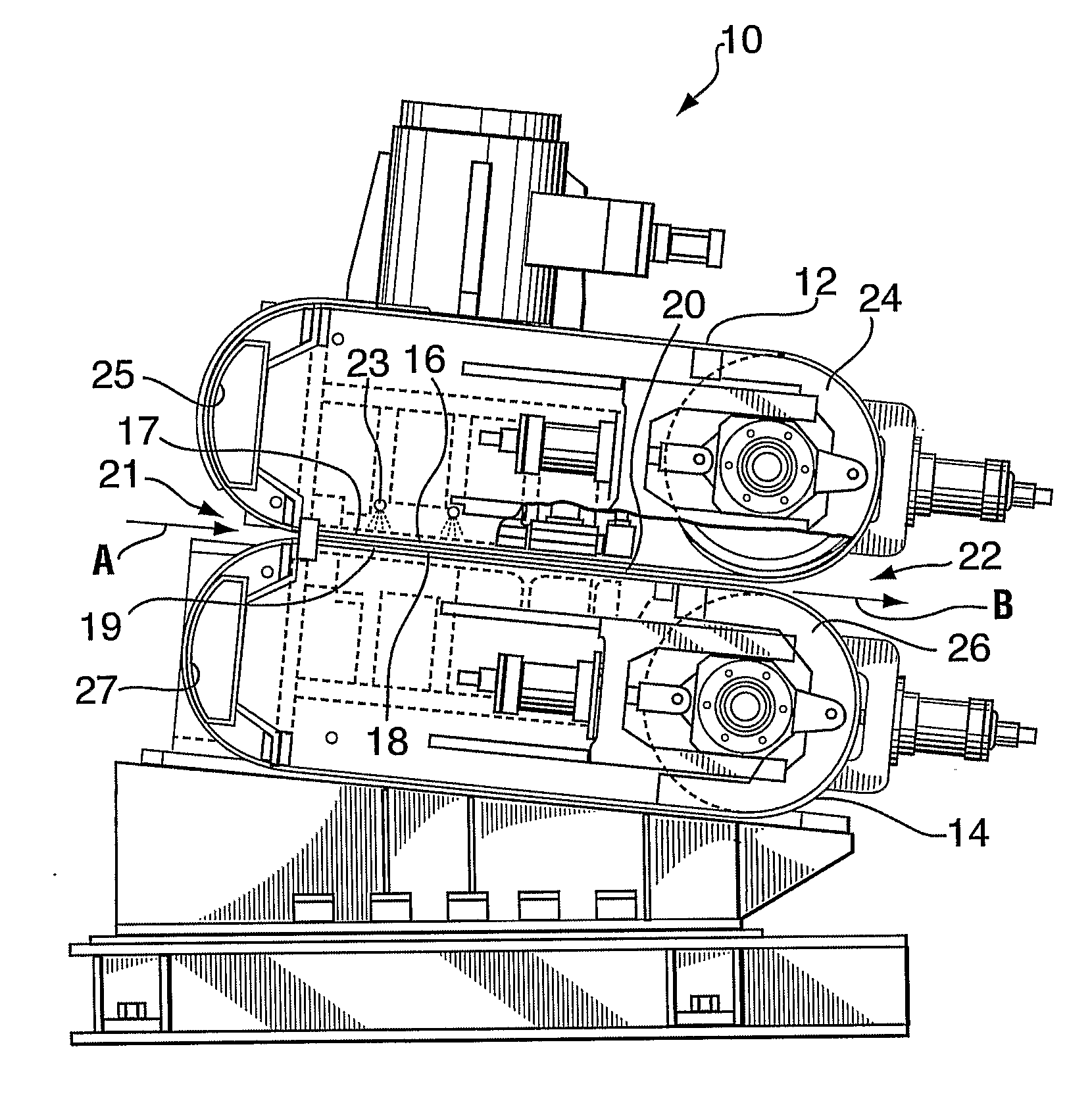
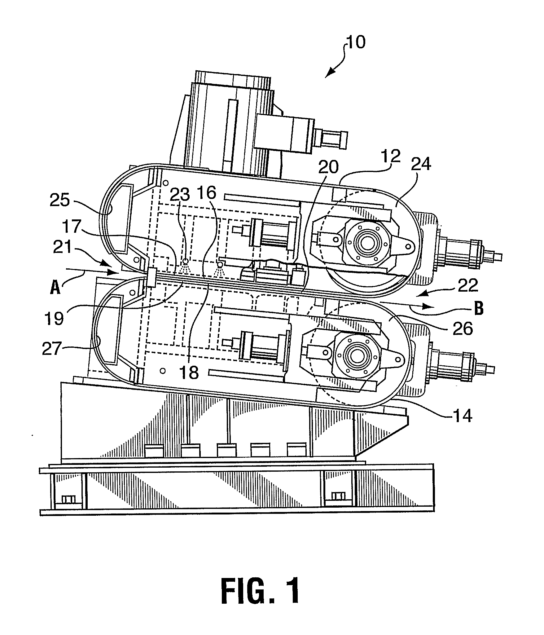
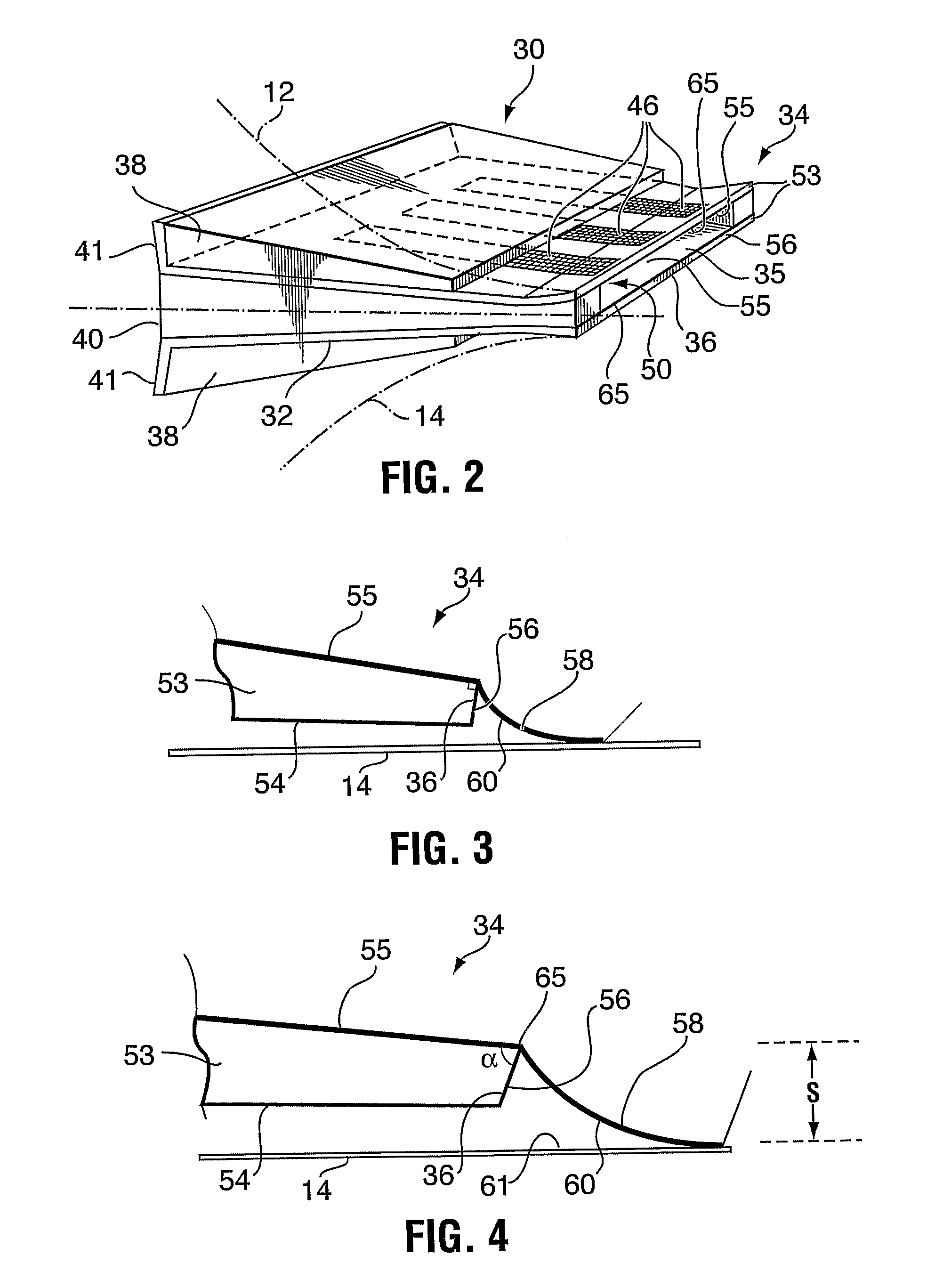
[0019] With regard to the design of the casting nozzle, the conventional nozzle employs a pair of projecting walls that define a molten metal channel between confronting inner metal-contacting surfaces. The channel has an exit at the tip of the nozzle where the projecting walls terminate at a flat end surface that extends at right angles to the inner metal-contacting surfaces. The walls also have outer surfaces that in use extend along the casting surfaces with a small gap. Using this type of nozzle, it was noticed that not only was the frequency of oscillation of the meniscus slow and erratic, but the oscillations bring the metal into contact with the end surfaces of the nozzle walls, causing oxide whiskers to form and build up, thereby causing further sticking and interference with the oscillations. The inventors found that this effect could be minimized or eliminated by “cutting-back” the end surface by a few degrees or more. This means that the end surface is caused to slope in a rearward direction from the line of contact with the inner metal-contacting surface to form an included angle (the angle within the material of the nozzle wall) of less than 88 degrees, more preferably 85 degrees or less, even more preferably 80 degrees or less, and most preferably 75 degrees or less. The minimum angle is preferably 15 degrees, because a smaller angle may be currently impractical for constructing the nozzle (although the desirable effect would still be apparent if the constructional limitations could be overcome). A more desirable lower limit for the cut-back angle is 30 degrees. An even more preferred lower limit is 45 degrees. Most preferably, the end surface of the nozzle wall is flat along its full length, i.e. from the intersections with the inner and outer walls, and from side to side across the nozzle. This has the advantage of making the striations more regular, particularly across the width of the casting cavity.
[0025] When the nozzle is of the closed type, the two walls forming the nozzle may be flat and parallel throughout their length, or they may be “flared” or “divergent” at the end, i.e. with the walls adjacent to the metal delivery end bending outwardly at an angle of usually no greater than about 8 degrees. This allows the walls to converge towards the casting surfaces by a small angle at the extreme end of the tip.

Problems solved by technology

However, in continuous strip casting, scalping may not be practical or economical and it is desirable to provide an article at the outset having a minimum of surface defects.
Such defects arise from the inevitable surface oxides that form on the meniscus surface of the molten metal where it exits the metal feeder to contact the moving casting surface.
As the meniscus is dragged along by the moving casting surface, the oxide film becomes strained and breaks, causing relatively large and visible surface defects of an irregular nature.
This not only affects the appearance of the cast article, but also can introduce structural weaknesses that cause rollability problems.
The defects are particularly critical in surface critical applications such as foil stock, can stock and automotive sheet, and can limit the speed of casting.

Method used


Image

  • Method Of And Molten Metal Feeder For Continuous Casting
  • Method Of And Molten Metal Feeder For Continuous Casting
  • Method Of And Molten Metal Feeder For Continuous Casting

Examples


example 1

[0050] The effects of different feeder tip angles were investigated on a single mold plane (water cooled) utilizing an open-topped box with a sliding bottom, to simulate the metal flow conditions from a stationary feeder tip onto a moving water cooled belt. The apparatus employed is shown schematically in FIG. 5 (plan view) and FIG. 6 (vertical longitudinal cross-section).

[0051] The metal was poured into a box 70 and a bottom plate 71 was pulled horizontally at predetermined speeds and molten metal temperatures, allowing the metal 75 to flow from an end 72 of the moving bottom plate onto a sheet steel mold 73, where it solidified progressively towards the moving bottom plate. The moving bottom plate (forming a thin slide) was made of the same material as the feeder tips used for continuous casting, and the right hand end was changed in geometry as shown in FIGS. 7A to 7D to study the effects of such changes on the solidified metal, such as meniscus break lines and other ingot surfa...

example 2

[0052] A series of casts were performed in a pilot scale belt caster using metal delivery nozzles having various cut-back angles. Casts were made on copper belts using aluminum alloy AA5754 cast 10 mm thick cast at a speed of 8 to 10 meters / minute.

[0053] The surface of the as cast strip was observed and photographed. The results are shown in FIGS. 8 to 12 and are summarized in Table 1 below.

TABLE 1Cut back angleFigure NumberObservation93 degrees8Severe oxide banding or foldsirregularly spaced about 30 mmapart88 degrees9Oxide banding or folds irregularlyspaced about 30 mm apart78 degrees10Regular fine banding about 1 mmspacing48 degrees11Regular fine banding about 1 mmspacing33 degrees12Regular fine banding about 1 mmspacing

[0054] Cut back angles of 93 and 88 degrees are outside the range of angles of the invention and the sheet cast using tips at such angles exhibit unacceptable oxide folds or banding. A spacing of 30 mm, typical of such bands, corresponds to a frequency of about...


PUM

PropertyMeasurementUnit
thicknessaaaaaaaaaa
included angleaaaaaaaaaa

Abstract

The invention provides a feeder for delivery of molten metal into a mold formed between confronting casting surfaces of a continuous casting machine. The feeder comprises a projecting nozzle tip having at least a lower wall provided with a molten metal-contacting inner surface, a generally flat outer surface and an end surface at an outer extremity of the tip extending between the inner and outer surface. The inner surface is generally flat and preferably slopes towards the outer surface considered in a direction moving towards the extremity of the tip at an angle of slope of no more than 8 degrees. The end surface is generally flat and extends from the inner surface to the outer surface at an acute angle of less than 88°, e.g. in the range of 15 to 80 degrees, relative to the inner surface in a direction away from the extremity of the tip. The feeder casts a metal sheet article having reduced surface defects caused by rupture of the metal oxide during casting.

Description

TECHNICAL FIELD [0001] This invention relates to the continuous casting of molten metals, preferably aluminum and aluminum alloys. More particularly, the invention relates to a method of introducing the molten metal into the casting cavity of a continuous caster and the design of a metal feeder used for this purpose. BACKGROUND ART [0002] Continuous casting of metals has been carried out for many years, e.g. by using a twin belt caster, twin roll caster or rotating block caster. Continuous casters of this kind usually have a horizontal, or slightly downwardly-sloping, casting cavity formed between two confronting and continuously rotating casting surfaces. The molten metal is introduced into one end of the casting cavity and it is cooled and solidified as it is drawn through the casting cavity by the rotating casting surfaces. A cast ingot, slab or strip of solidified metal emerges from the casting cavity at the opposite end. [0003] Molten metal is introduced into the casting cavity...

Claims


Application Information

Patent Timeline
Patent Type & Authority Applications(United States)
IPC IPC(8): B22D11/06B22D11/00B22D41/00
CPCB22D11/0642B22D11/0605B22D11/103B22D11/06
Inventor SULZER, JOHNGALLERNEAULT, WILLARD MARK TRUMAN
Owner NOVELIS INC
Learn More