
System and method for selecting an operating level of a heating, ventilation, and air conditioning system

a technology of heating ventilation and air conditioning system, which is applied in the direction of heating types, lighting and heating apparatus, instruments, etc., can solve the problems of troublesome clock-thermostats, high energy consumption, and high energy consumption, and achieve the effect of reducing system strain and increasing efficiency

Inactive Publication Date: 2008-04-10
TELKONET INC
View PDF4 Cites 160 Cited by
  • Summary
  • Abstract
  • Description
  • Claims
  • Application Information

AI Technical Summary

Benefits of technology

"The present invention provides a method and apparatus for selecting an operating level of an HVAC system based on estimated drive durations. The method involves estimating the time it will take to drive the system to a desired temperature using a prior drive operation and a predefined minimum and maximum drive time. The estimated drive time is based on the temperature at the beginning, midpoint, and end of the prior drive operation. The method can select the operating level based on the relationship between the estimated drive time and the minimum or maximum drive time. The apparatus includes a sensor to measure the temperature and a controller to activate the system at the selected operating level. The technical effect of the invention is to improve efficiency and reduce strain on the system by ensuring drive times fall within recommended limits."

Problems solved by technology

A problem with such the thermostats is that the temperature is maintained at the user set point whether people are present or not, using costly natural resources.
Heating or cooling when people are not present wastes a great deal of these resources.
Problems with this approach are that the programming of the clock-thermostats is troublesome, and moreover that, even when the programming is done correctly, people's schedules change and thus often do not match the preprogrammed times.
The problem with these thermostats is the second temperature is often either too far away from the first temperature to provide satisfactory comfort when someone returns to the room, or too close to the first temperature to achieve adequate energy savings.
Further, enclosed space and ambient conditions change constantly, so these thermostats are very difficult to regulate for optimal energy savings versus comfort trade-offs.
Even if a user could figure out the optimum second thermostat setting for comfort and maximum energy savings at a given time, conditions constantly change and that setting may quickly become non-optimal.
One problem with current automatic and manual / automatic thermostat implementations as described above is that typical operating level selection logic does not take into consideration the operating characteristics of the HVAC system in the areas of efficiency and longevity.
Many HVAC system manufacturers do not recommend operating the compressor for less than a minimum amount of time or for longer than a maximum amount of time.
Failure to follow such guidelines can significantly shorten the life of the HVAC system.
Operating times that are too short due to improper speed selection may cause damage to the HVAC system or, if the HVAC system has a built-in safety check that will not turn the system off until the minimum run time is met, the room temperature may continue to be driven down or up even after the user's setpoint has been reached.
This can result in significant overshoot of the setpoint temperature and, correspondingly, user dissatisfaction.
This phenomenon is termed “short cycling” and can also greatly reduce dehumidification effectiveness and affect the uniformity of the temperature in the room.
Failure to take into account both the relative system efficiency and the manufacturer recommended operating parameters of the HVAC system when selecting a cooling or heating speed may result in unnecessarily high energy usage, room occupant discomfort, damaged to soft goods in the room, and damage to the HVAC system.

Method used


Image

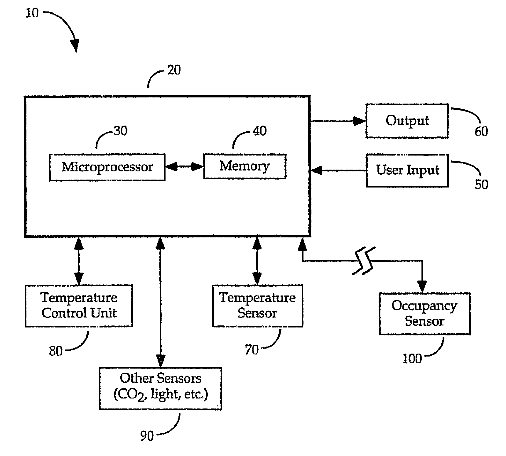
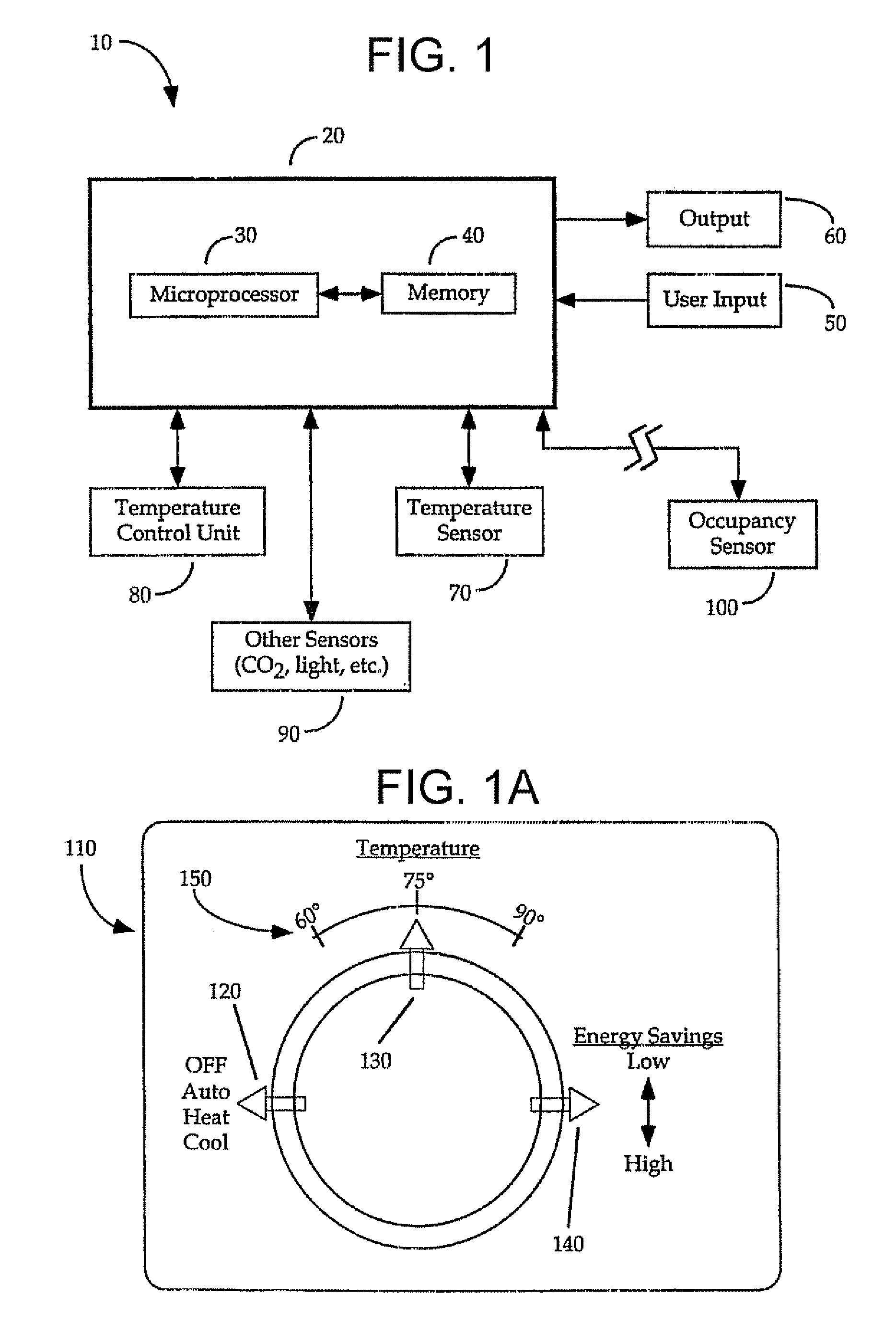
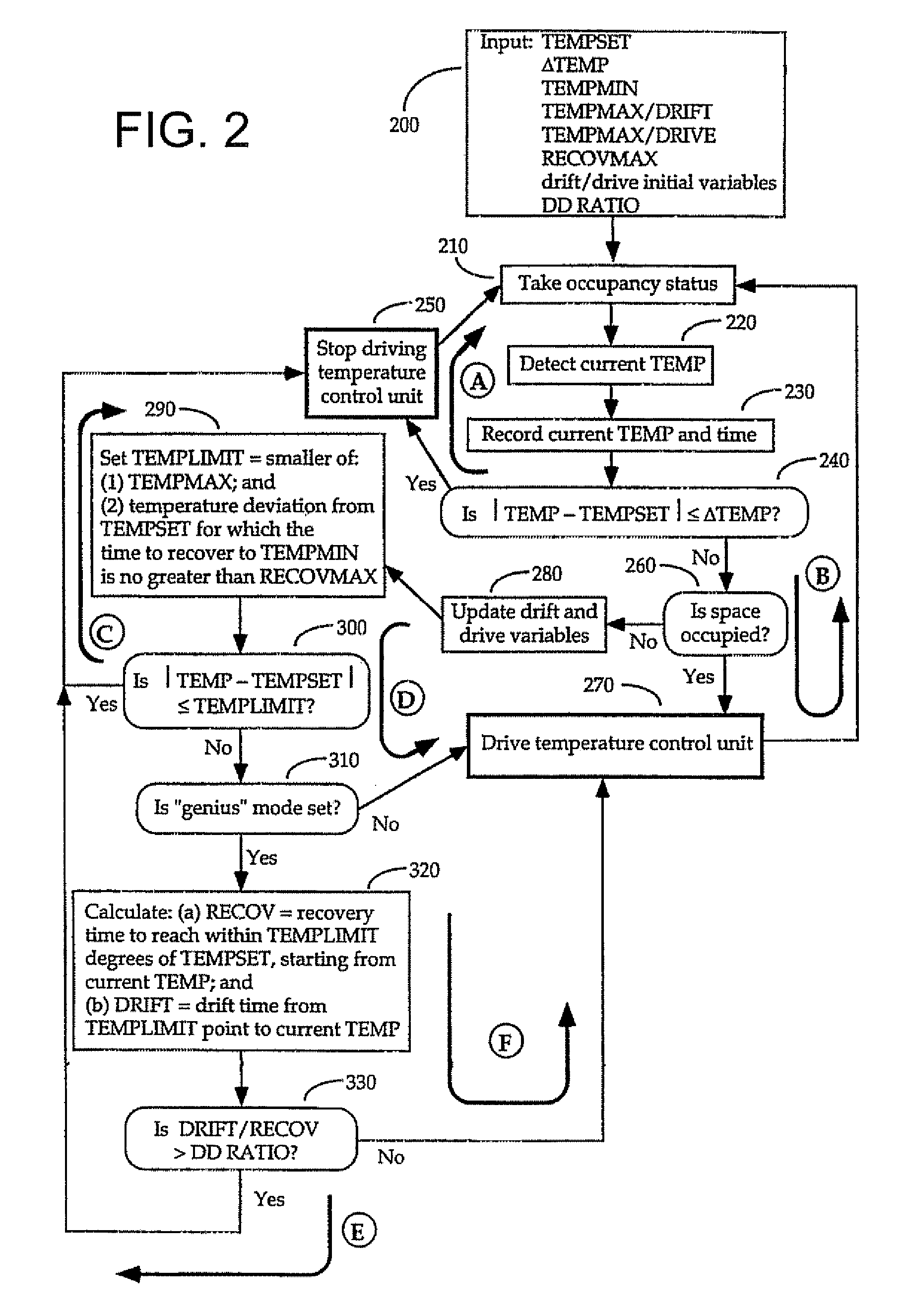
  • System and method for selecting an operating level of a heating, ventilation, and air conditioning system
  • System and method for selecting an operating level of a heating, ventilation, and air conditioning system
  • System and method for selecting an operating level of a heating, ventilation, and air conditioning system

Examples


Embodiment Construction

[0041]The present invention now will be described more fully hereinafter with reference to the accompanying drawings, in which preferred embodiments of the invention are shown. This invention may, however, be embodied in many different forms and should not be construed as limited to the embodiments set forth herein; rather, these embodiments are provided so that this disclosure will be thorough and complete, and will fully convey the scope of the invention to those skilled in the art. Like numbers refer to like elements throughout.

[0042]Embodiments of the invention are described herein in conjunction with thermostatic climate control systems capable of estimating recovery times in order to drive the temperature back to, or within range or, the user setpoint within a specified recovery time. However, it should be appreciated that systems and methods of embodiments of the invention may be used in conjunction with any temperature management or climate control system capable of driving ...


PUM


Abstract

A method and apparatus for selecting an operating level of an HVAC system uses historic and predicted drive durations to ensure that drive periods fall within the recommended minimum and maximum drive times, thereby increasing efficiency and reducing strain on the system. The method comprises the steps of: receiving a minimum and a maximum drive time of the HVAC system; determining a current temperature of a room; estimating, based on a prior drive operation of the HVAC system, a time to drive the current temperature to a predefined desired temperature; and selecting an operating level of the HVAC system based on a relationship of the calculated drive time to the minimum drive time and the maximum drive time. Selecting the operating level comprises at least one of: selecting a fan speed; activating a compressor; activating an auxiliary or emergency heating element; or activating an auxiliary or emergency cooling element.

Description

FIELD OF THE INVENTION[0001]This invention relates to the temperature and other climate control of interiors of buildings, and in particular to a system for controlling the temperature of an environment according to predetermined criteria including the presence or absence of people, programmable comfort ranges, and programmable time tolerances to reach those comfort ranges.BACKGROUND OF THE INVENTION[0002]In conventional temperature or climate control systems (e.g. heating, ventilating and air conditioning systems, referred to herein generally as “HVAC”), thermostats are used to control when the HVAC system turns on and off. The user presets a desired temperature (or “user set point”), and when the temperature of the controlled space is different from the preset temperature, the HVAC system heats or cools the air until the preset temperature is reached.[0003]Thus, conventional enclosed space thermostats are merely on / off switches with a sensor to measure the enclosed space temperatu...

Claims


Application Information

Patent Timeline
Patent Type & Authority Applications(United States)
IPC IPC(8): B60H1/00
CPCB60H1/00892F24F11/0012G05D23/1919F24F11/0034F24F11/006F24F11/0015F24F11/30F24F2110/10F24F2110/20F24F2120/10F24F11/62F24F11/77F24F2120/00F24F11/46F24F11/64F24F11/526F24F11/86F24F11/38F24F11/56F24F11/65
Inventor KREBS, STEVEPITT, RONALD L.ZIRPOLI, ROBERT
Owner TELKONET INC
Learn More