Wind power converting apparatus and method

a technology of wind power conversion and wind power, which is applied in the direction of machines/engines, renewable energy generation, greenhouse gas reduction, etc., can solve the problems of wind generators, machines that convert wind power into electrical, mechanical or thermal energy, and are limited in the speed of the wind, and few attempts have produced any technology available or effectiv

Inactive Publication Date: 2008-04-10
CALIFORNIA ENERGY & POWER
View PDF20 Cites 48 Cited by
  • Summary
  • Abstract
  • Description
  • Claims
  • Application Information

AI Technical Summary

Benefits of technology

[0008]These Functions Occur Substantially simultaneously from the working surfaces provided, processing wind into a controllable flow direction, with increased velocity. The device of the present invention collects, constricts, increases the fluids speed, and directs that resultant flow into the working side of a vertical axis wind turbine, or equivalent power converter.

Problems solved by technology

Wind generators, machines that convert the wind into electrical, mechanical or thermal energy, known in the art are limited to the speed of the wind.
Although there are references in prior art of attempts to produce wind concentrating shrouds, barriers and airfoils to divert wind into the device at presumably higher speed to produce more power available for conversion, few attempts have produced any technology that is available or effective.

Method used


Image

  • Wind power converting apparatus and method
  • Wind power converting apparatus and method
  • Wind power converting apparatus and method

Examples


Embodiment Construction

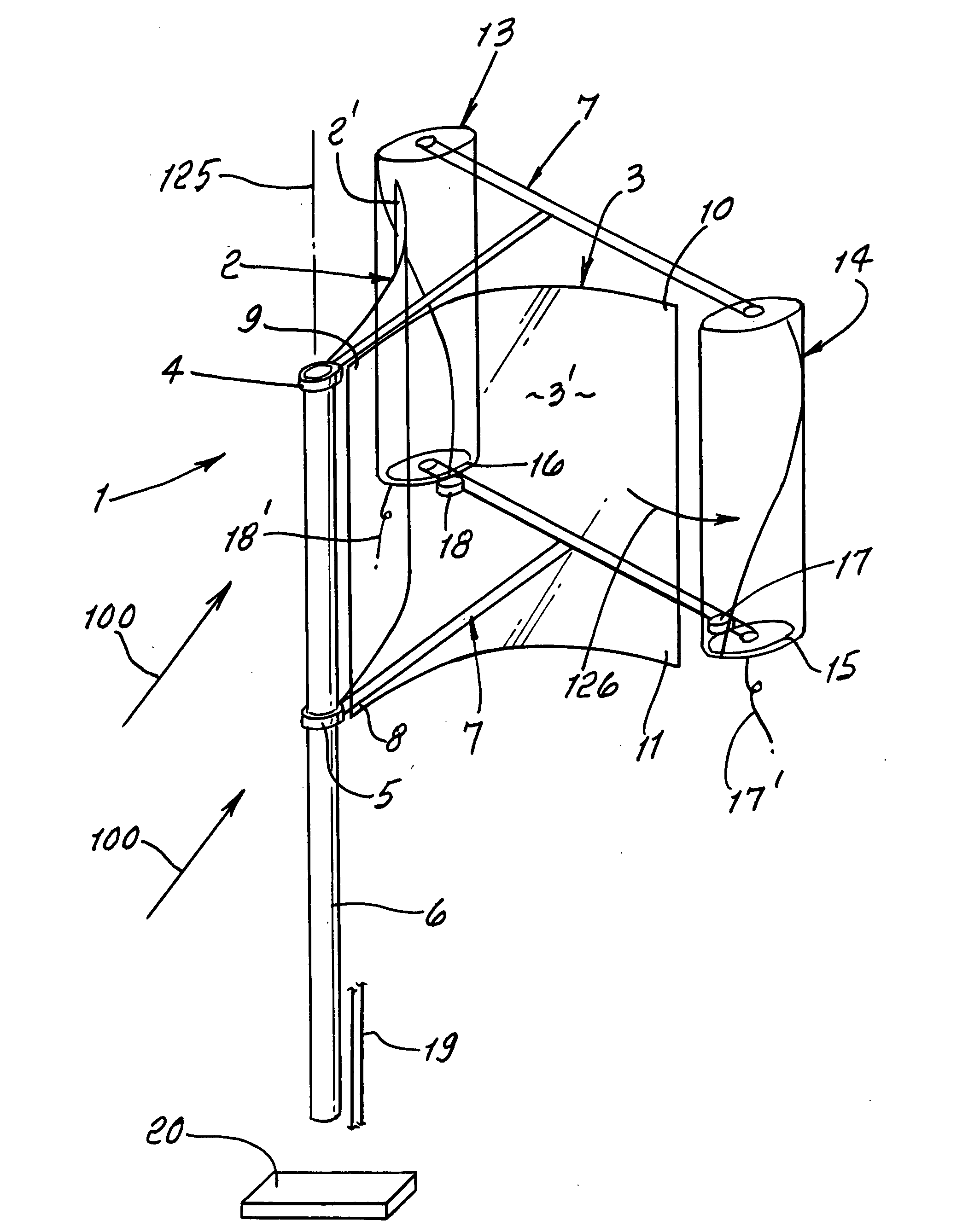
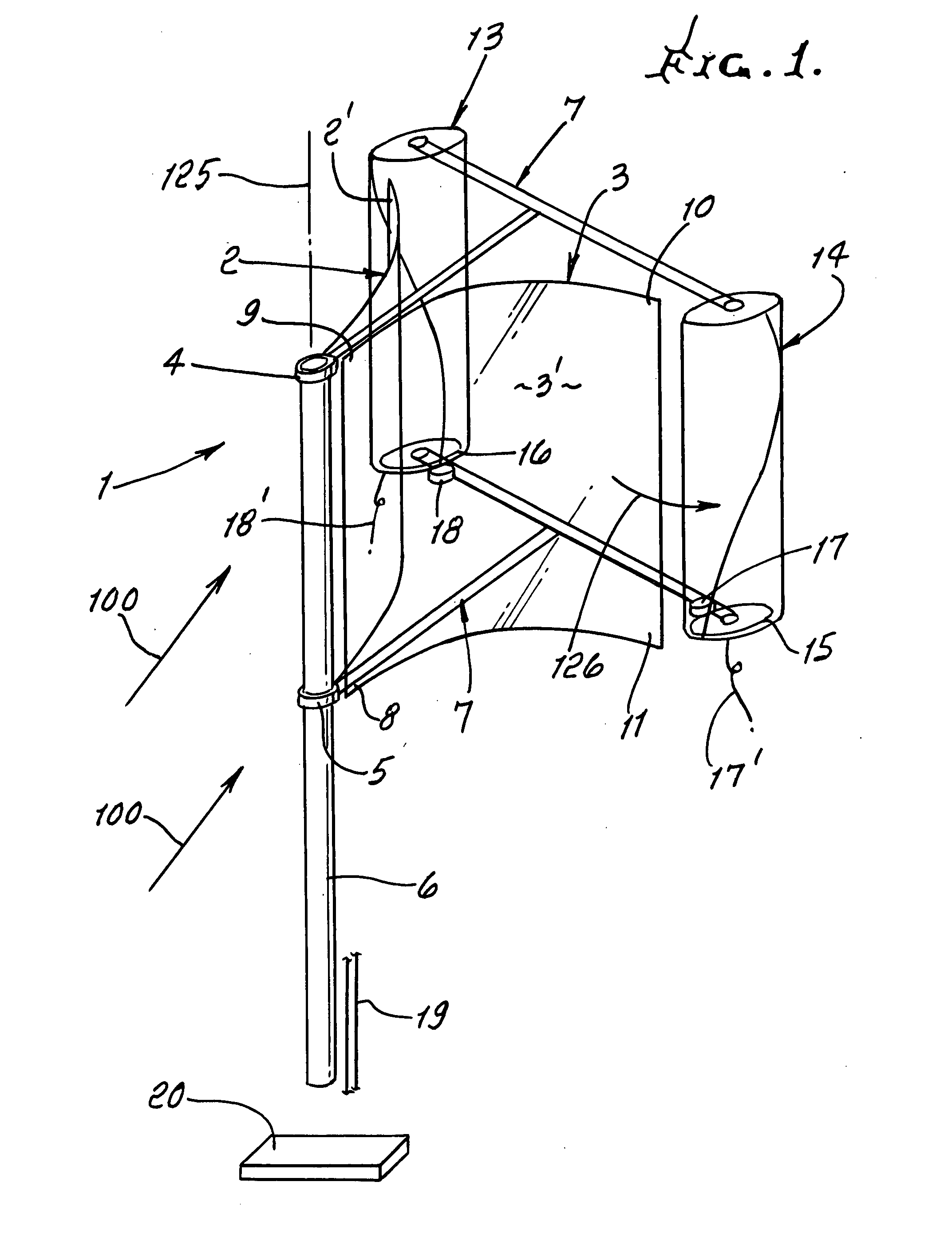
[0030]FIG. 1 shows the down-wind, or aft orientation of the preferred device 1. The control surfaces, 2′ and 3′ of baffles 2 and 3 are curved and act on incident wind indicated by arrows 100. The baffles are carried by frame 7 that pivotally reacts to the wind and orients itself aft of the frame pivot bushings 4 and 5 on upright stand 6. Each control surface 2′ and 3′ presents the most stable lowest potential energy position when exposed to wind, as shown. Initial power present in the wind is used for self-orientation. Upon any wind from any other direction impinging on the device, a difference in pressure is experienced along the vertical axis of the mounting stand 6. This uneven pressure on each curved control surface 2′ and 3′ acts to rotate the device about the axis 125 of the stand 6, orienting the device to the most aft position enabled by the frame 7 relative to the pivot bushings 4 and 5. The wind gathered by surfaces 2′ and 3′ is concentrated and respectively supplied to th...


PUM


Abstract

In combination a frame having an upright axis, at least one wind turbine carried by the frame in offset relation to said frame axis, to rotate relative to that axis, at least one baffle oriented by the frame to collect incident wind and re-direct such wind into the turbine.

Description

BACKGROUND OF THE INVENTION[0001]This invention relates generally to wind turbines, and more particularly to enhancement of the efficiency and power output of such devices by more efficient utilization of wind power.[0002]Wind generators, machines that convert the wind into electrical, mechanical or thermal energy, known in the art are limited to the speed of the wind. The resource of wind is described by those learned in the art as having a power equal to one half the density of the fluid through a swept area times the cube of the fluid's velocity. The important relationship between the speed of the wind, and the power available in the wind at a given wind speed firstly determines the actual productivity of a wind generator.[0003]The wind generator's ability to extract work from the wind describes its power coefficient (Cp). Knowing these two quantities, the power available in the wind (P), and the ability to extract work define the physical outputs of a given wind generator.[0004]...

Claims


Application Information

Patent Timeline
Patent Type & Authority Applications(United States)
IPC IPC(8): F03B15/06
CPCY02E10/74F03D3/0454F03D15/00F03D9/25F03D3/02
Inventor KINKAID, CHRISTOPHER PIPER TOBYCOYE, PETER L.
Owner CALIFORNIA ENERGY & POWER
Why Eureka
Try Eureka