

Fuel cell system
a fuel cell and system technology, applied in the direction of fuel cells, reactant parameter control, electrical equipment, etc., can solve the problem that the methanol aqueous solution cannot be disadvantageously controlled to the appropriate concentration
- Summary
- Abstract
- Description
- Claims
- Application Information
AI Technical Summary
Benefits of technology
Problems solved by technology
Method used
Image

Examples
first embodiment
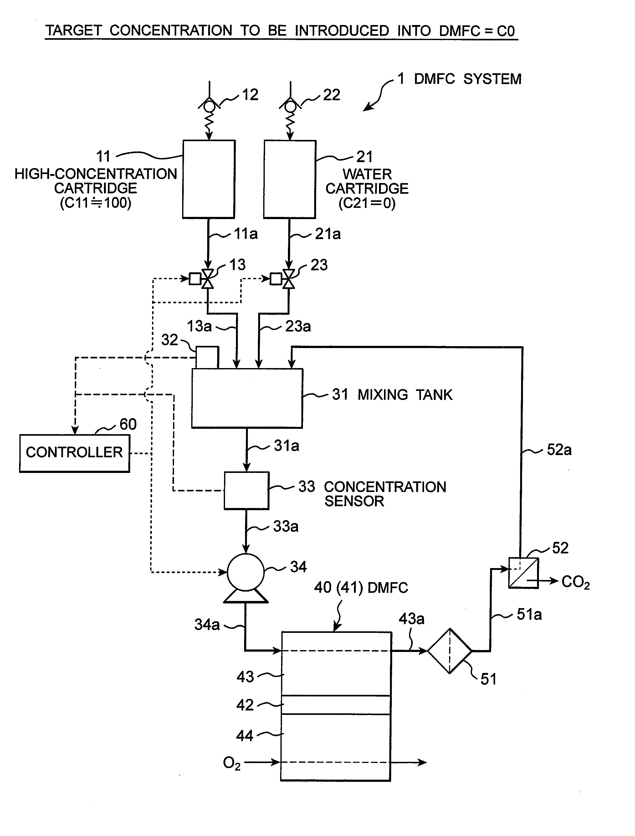
[0035]Now, a DMFC system 1 (fuel cell system) according to a first embodiment of the invention will be described with reference to FIG. 4.
[0036]As shown in FIG. 4, the DMFC system 1 mainly includes a high-concentration cartridge (first cartridge) 11, a water cartridge 21, a mixing tank (mixer) 31, and a DMFC (fuel cell) 40.
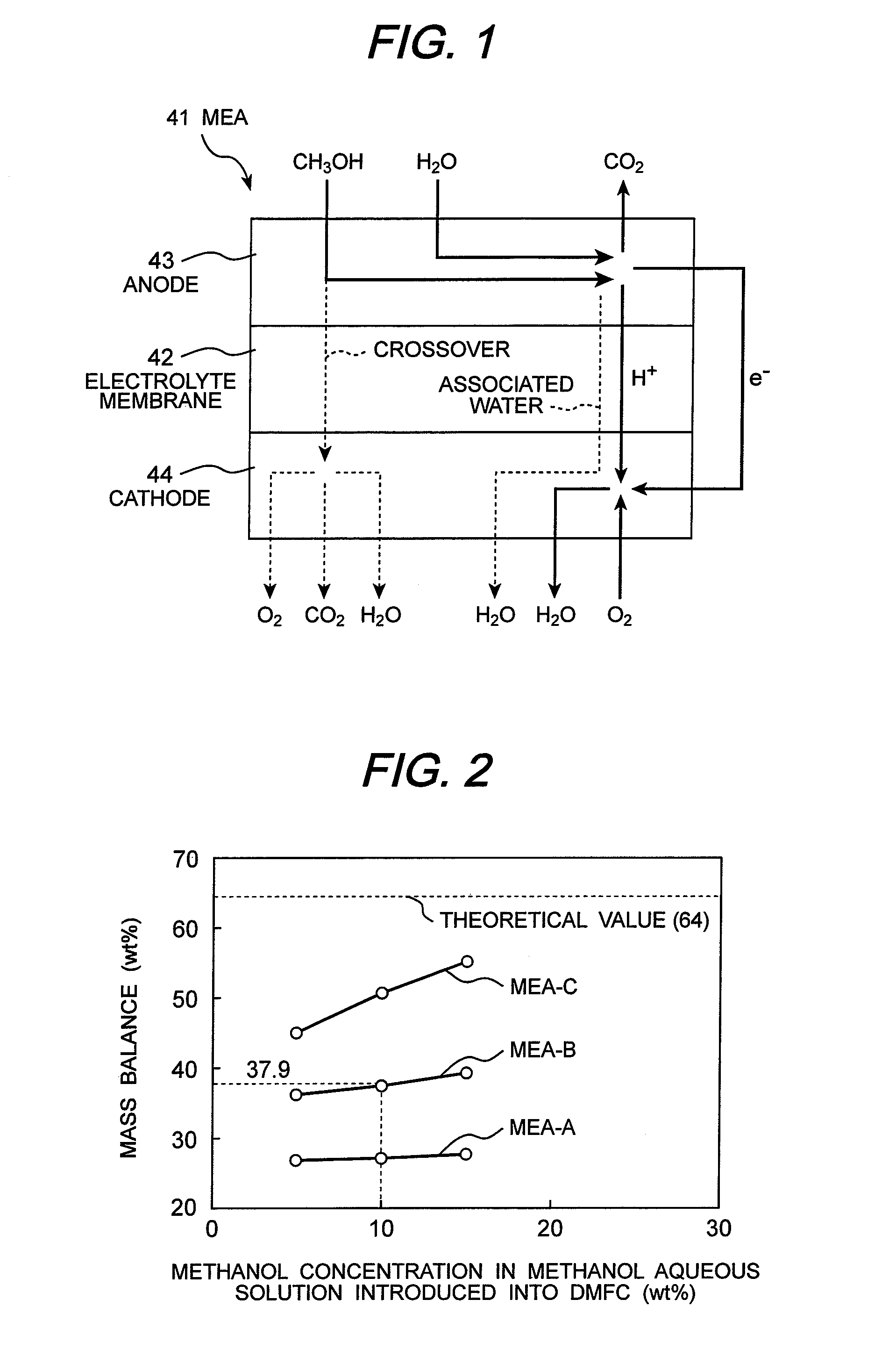
[0037]In the first embodiment, and in second to fourth embodiments to be described later, a methanol aqueous solution having the target concentration C0 (target fuel concentration) of methanol is introduced into the anode 43 of the DMFC 40.
[0038]In the high-concentration cartridge 11, a methanol aqueous solution (first liquid fuel) having a concentration C11 (wt %) (C011≈100, first fuel concentration) is sealed. Such a high-concentration cartridge 11 is adapted to be detachably attached on a dock (not shown) of the DMFC system 1.
[0039]The high-concentration cartridge 11 and the water cartridge 21 differ in, for example, shape, and have respective pipes 11a, 21a, a...
second embodiment
[0062]Next, a DMFC system 2 according to a second embodiment will be described with reference to FIG. 2. The different points of this embodiment from the first embodiment will be mainly explained.
[0063]As shown in FIG. 5, the DMFC system 2 includes a high-concentration cartridge 11 (C01411 (C11≈100), and a low-concentration cartridge 24 (024≦C0, second fuel concentration), instead of the water cartridge 21 (C21=0). Both of the high-concentration cartridge 14 and the low-concentration cartridge 24 are adapted to be detachably installed on the dock (not shown) of the DMFC system 2.
[0064]In the high-concentration cartridge 14 (first cartridge), a methanol aqueous solution (first liquid fuel) having a concentration C14 (wt %) is sealed. In the low-concentration cartridge 24 (second cartridge), a methanol aqueous solution (second liquid fuel) having a concentration C24 (wt %) is sealed.
[0065]The outlet of the cathode 44 of the DMFC 40 is connected to the mixing tank 31 via a pipe 44a, a ...
third embodiment
[0075]Next, a DMFC system 3 according to a third embodiment will be described with reference to FIG. 6. The different points of this embodiment from the second embodiment will be mainly explained.
[0076]The DMFC system 3 includes a target concentration cartridge 25 (mixer), instead of the low-concentration cartridge 24 (024≦C0). The target concentration cartridge 25 is detachably installed on the dock (not shown) of the DMFC system 3, and seals therein the methanol aqueous solution having the concentration C25 (wt %) (target concentration liquid fuel) equal to the target concentration C0.
[0077]The DMFC system 3 does not include the mixing tank 31 (see FIG. 5) and the downstream end of the opening / closing valve 23 is connected to the concentration sensor 33.
[0078]Like the case where the concentration C24 of the methanol aqueous solution in the low-concentration cartridge 24 is set to the target concentration C0 in the second embodiment, the methanol aqueous solution having the target ...
PUM
 Abstract
Description
Claims
Application Information