Pleated heat and humidity exchanger with flow field elements

a technology of heat and humidity exchanger and flow field element, which is applied in the direction of carburettors, lighting and heating apparatus, mixing methods, etc., can solve the problems of high cost materials, general less compactness than plate-type devices, and the disadvantage of high pressure drop of hollow tube humidifiers

Inactive Publication Date: 2008-04-10
DPOINT TECH
View PDF18 Cites 111 Cited by
  • Summary
  • Abstract
  • Description
  • Claims
  • Application Information

AI Technical Summary

Benefits of technology

[0017] The flow field elements define a plurality of discrete fluid flow channels within the folds of the pleated membrane cartridge. In preferred embodiments the flow field elements are individual discrete structures that are disposed in each of the folds. They can be attached to the membrane or not. The membrane is water-permeable, typically substantially gas impermeable, can be pleated and is suitable for use in fuel cell applications, ERV applications, or the particular end-use application. In addition to more conventional water-permeable membranes, porous membranes that contain one or more hydrophilic additives or coatings can be used.

Problems solved by technology

Other types of exchangers such as hollow tube and enthalpy wheel humidifiers typically use high cost materials and are generally less compact than plate-type devices.
Hollow tube humidifiers also have the disadvantage of high pressure drop, and enthalpy wheels tend to be unreliable because they have moving parts.
In hot and humid climates, energy is wasted when the cooled air from the building is exhausted.
If buildings are too humid, ERVs will lower humidity levels, reducing the likelihood of mould, bacteria, viruses, and fungi which cause sickness, absenteeism and lost productivity.
On the other hand, in cold dry climates, energy is wasted when the warm air from the building is exhausted, plus there can be an additional issue of the incoming air stream being too dry.
However, in this type of device there is a large number of joints and edges that need to be sealed.
As a result such devices can be labor intensive and expensive to manufacture.
Also their durability can be limited, with potential delamination of the membrane from the frame and failure of the seals resulting in leaks and poor performance and cross-over contamination (leakage between streams).
In ERV applications existing planar plate-type ERV cores typically do not produce the total enthalpy exchange required and they are typically not durable in cold weather climates.
Although the reinforcing material used in the pleated humidifying apparatus, described in the aforementioned patent application, allows introduction of gas into the inner portion of the pleated structure, it does not provide controlled or directional gas flow distribution over the membrane surface.
Furthermore, the fluid flow paths through or across such materials tend to be quite tortuous and turbulent, so the flow can be quite restricted and the pressure drop across the apparatus can be significant.

Method used


Image

  • Pleated heat and humidity exchanger with flow field elements
  • Pleated heat and humidity exchanger with flow field elements
  • Pleated heat and humidity exchanger with flow field elements

Examples


Embodiment Construction

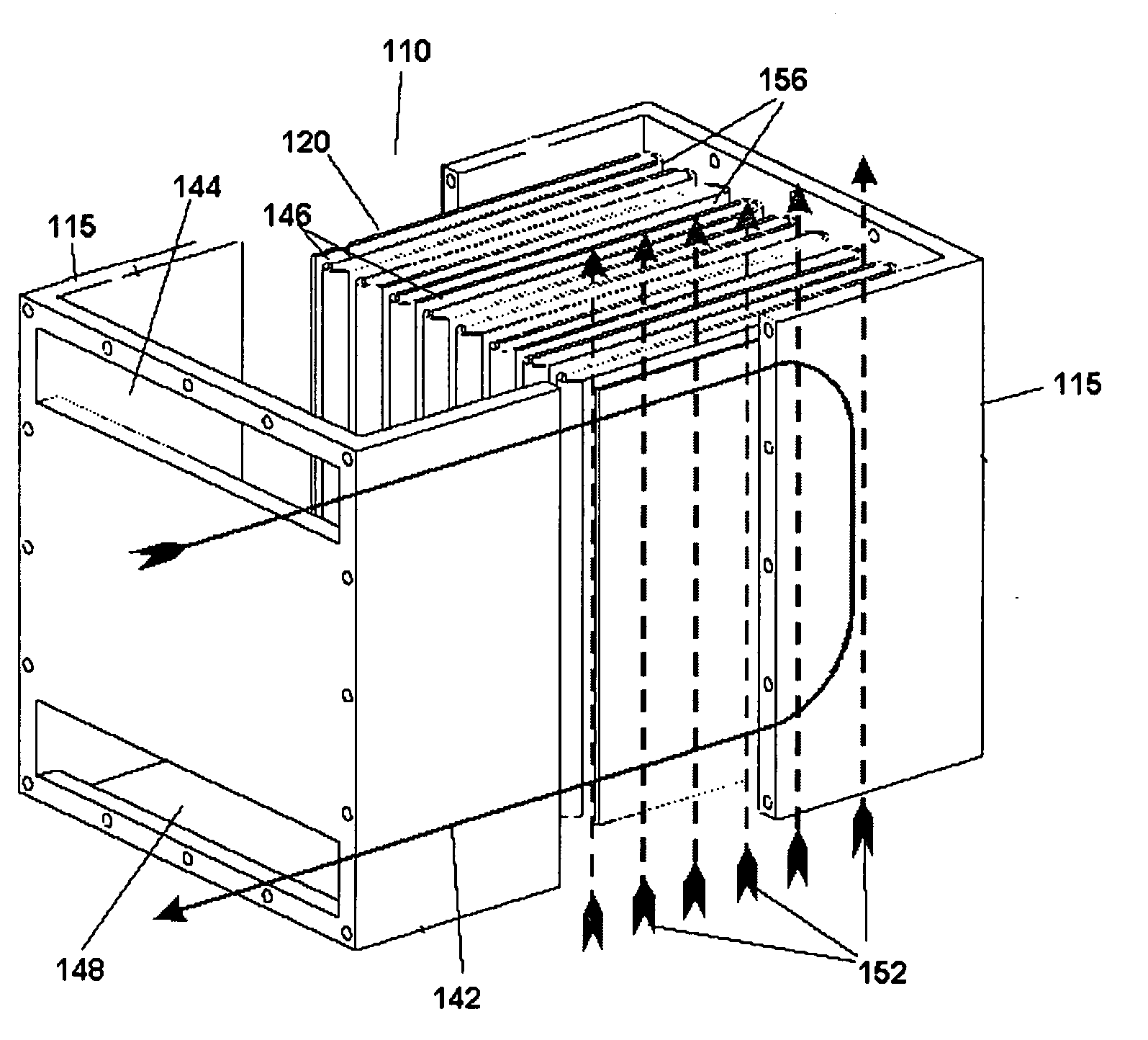
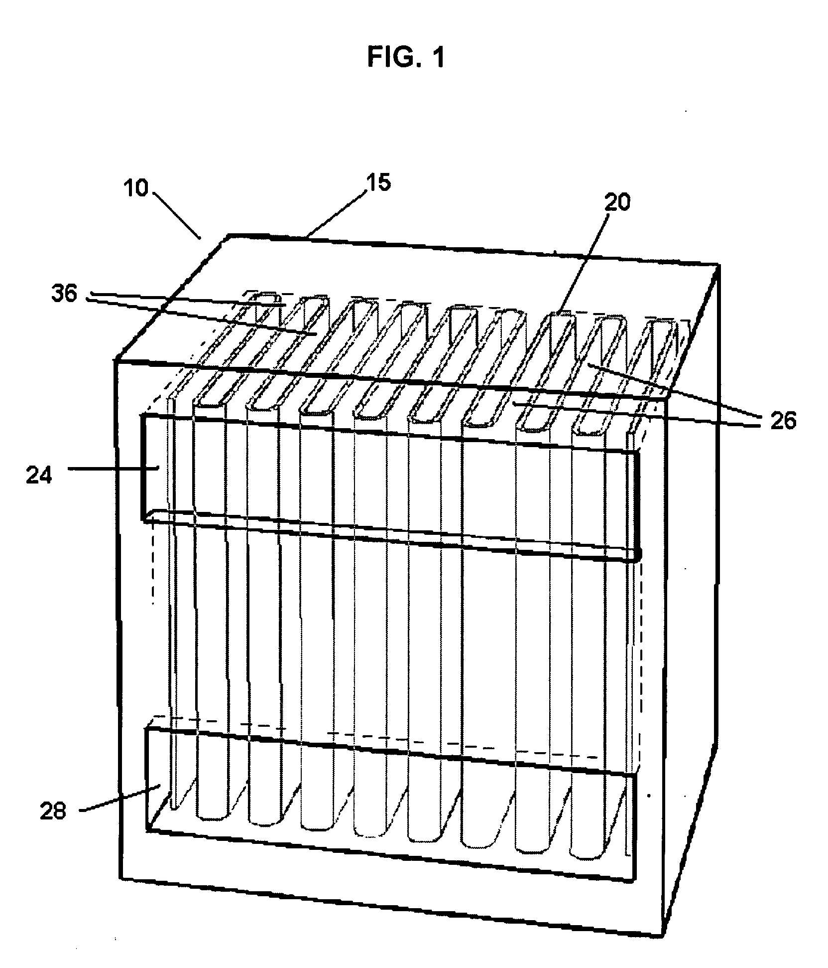
[0035] The present invention relates to a heat and humidity exchanger comprising a pleated membrane cartridge that is enclosed in a housing. The cartridge comprises a pleated water-permeable membrane, sealed around the perimeter, and flow field elements that are disposed within the folds (pleats) on at least one side of the pleated membrane. Folds on the other surface of the water-permeable membrane can also have flow field elements disposed therein. The membrane fold wraps around and generally contacts both faces of the flow field element. When there are flow field elements on both sides of the membrane, the flow field elements are effectively interleaved on opposite sides of the pleated membrane.

[0036] The flow field elements are for directing fluid streams across the surface of the membrane that is in contact with the element. The open-channels of the flow field element offer less restriction to fluid flow than the netting or meshes used to support the membrane in existing pleat...


PUM

PropertyMeasurementUnit
perimeteraaaaaaaaaa
hydrophilicaaaaaaaaaa
humidityaaaaaaaaaa

Abstract

A heat and humidity exchanger comprises a pleated membrane cartridge disposed in a housing. The cartridge comprises a pleated water-permeable membrane via which heat and humidity can be transferred between two fluid streams. A flow field element is disposed within some or all of the folds of the pleated membrane, for directing the stream over the inner surfaces of the folds. The flow field path defined by the flow field element enhances flow distribution across one or both membrane surfaces, controlling the relative flow paths of the two streams on opposite sides of the membrane and reducing the pressure drop across the heat and humidity exchanger. The flow field elements provide improved water transfer and allow for a more compact device. The flow field elements can also assist in supporting the pleated membrane and controlling the pleat spacing within the pleated membrane cartridge. The heat and humidity exchanger is particularly suitable for fuel cell and energy recovery ventilator (ERV) applications.

Description

FIELD OF THE INVENTION [0001] The present invention relates to a heat and humidity exchanger. The heat and humidity exchanger includes a cartridge comprising a pleated water-permeable membrane. Flow field elements are disposed within the folds of the pleated membrane to direct the flow of fluid streams across opposing surfaces of the membrane between at least one inlet and outlet on each side. In addition to defining the fluid flow paths within the folds, the flow field elements provide support for the membrane and control the pleat spacing within the cartridge. The flow field elements improve the flow distribution of the fluids across the membrane surfaces, improve the heat and humidity exchange and reduce the pressure drop, therefore allowing the exchanger to be more compact. The heat and humidity exchanger is particularly suitable for fuel cell applications and energy recovery ventilator (ERV) applications. BACKGROUND [0002] Heat and humidity exchangers (also sometimes referred t...

Claims


Application Information

Patent Timeline
Patent Type & Authority Applications(United States)
IPC IPC(8): H01M8/04B01F3/04F24F1/0059
CPCB01D53/268F24F1/0059F24F3/147F24F2003/1435F28D9/0025Y02E60/50H01M8/04014H01M8/04074H01M8/04126H01M8/241F28D21/0015
Inventor DEAN, JAMES FRANKLINCOMEAULT, CHAD EVERETTKADYLAK, DAVIDMONTIE, GREG
Owner DPOINT TECH
Why Eureka
Try Eureka