
Vehicle cabin heating cooling and ventilation system

a ventilation system and vehicle cabin technology, applied in the field of tactical and non-tactical vehicle cabins, can solve the problems of increased manufacturing costs of vehicles, increased vehicle weight and consumption of valuable cabin space, and engine running of vehicles

Active Publication Date: 2008-04-10
HDT EXPEDITIONARY SYST
View PDF15 Cites 56 Cited by
  • Summary
  • Abstract
  • Description
  • Claims
  • Application Information

AI Technical Summary

Benefits of technology

[0018]According to still yet another aspect of the present invention, an air treatment system for a vehicle includes a refrigerant compressor selectively coupled to a first power source of the vehicle. A first heat exchanger communicates with an interior space defined in the vehicle. A second heat exchanger communicates with an environment exterior to the vehicle. A valve assembly is provided. In a first setting, the valve assembly couples an inlet of the refrigerant compressor to an outlet of the first heat exchanger and an outlet of

Problems solved by technology

One such challenge is the redesign of combat vehicles to safely carry personnel and or cargo.
There are several disadvantages in using such engine driven independent systems for the heating and cooling of a vehicle interior.
First, using separate heating and cooling systems requires the use of twice as many fluid conduits and heat exchangers.
Having two sets of fluid lines and heat exchangers not only incurs additional expense in the manufacture of the vehicle, but also contributes to the overall vehicle weight and consumption of valuable cabin space.
It can be seen that cost, weight, and space are all important concerns.
Yet another disadvantage of the conventional heating, cooling, ventilation system is that the engine of the vehicle must be running in order to produce heat.
Furthermore, there is usually some delay in the production of heat under cold weather starting conditions.
This delay in heat production can be inconvenient for the driver and passengers in the cabin.
In such cases, waiting for the engine to sufficiently warm to defrost the front windshield can increase the time needed before the vehicle can be driven
Yet another disadvantage of a conventional heating, cooling, ventilation system is that the engine must be running to provide the mechanical rotational energy for air conditioning compressor and engine water pump rotation.
This loss of engine rotational energy for air conditioning and engine water pump operation stops interior heating, cooling and ventilation.
Cold weather clothing can help retain body heat but wearing such clothing is both cumbersome and restrictive.
Therefore, lack of heat when the engine is off can also be a problem.
In many instances personnel are unable to remove protective clothing to aid in reducing body temperature.
As a result, the interior vehicle temperature can become extreme within minutes.
Prolonged exposure to elevated temperatures can cause physical stress that ultimately impairs the ability of personnel to perform.
Yet another disadvantage of present conventional heating, cooling, ventilation systems is that fresh air filtration systems provide limited protection from harmful gasses and biological contaminants.
In many cases carbon based filters and particulate filters are undersized for ease of integration and to keep consumer costs low, and thus only limited protection is provided.
In addition, airflow density and velocity through the filters is not managed thus producing off gassing and reducing overall capacity.
Yet another disadvantage of present conventional heating, cooling, and ventilation systems, particularly for military vehicles, is the use of externally mounted Nuclear, Biological, and Chemical (NBC) filtration systems.
This approach exposes the ventilation over pressurization system to heat and cold, increasing the load on the vehicle heating and cooling system.
In addition, an exterior mounted system is outside of standard vehicle protective armor and may require additional shielding or armor for protection.
This further contributes to vehicle weight, time required to service the system, and mounting complexity.
Another disadvantage of an exterior mounted system is that it provides additional surfaces where weapons such as hand grenades could become stuck or lodged.
Yet another disadvantage of the conventional heating, cooling, ventilation system is that vehicle NBC ventilation over pressurization systems regulate the interior pressure of the vehicle by increasing or decreasing the over pressurizing air flow.
These systems do not monitor the density or velocity of the air moving through an NBC filter system.
Yet another disadvantage of the conventional heating, cooling, ventilation system is the introduction into the vehicle interior of external filtered over pressurization air.
The method of mixing the ambient filtered air flow before passing the ambient air through a heat exchanger is less efficient than introducing the ambient air directly to the heat exchanger.
Yet another disadvantage of the conventional heating, cooling, and ventilation system is the lack of airflow control for use with a military personnel cooling vest.
The lack of a conditioned airflow control can impede the efficient operation of the cooling vest.
As with a high interior vehicle temperature, insufficient vest cooling can cause physical stress that ultimately impairs the ability of personnel to perform.

Method used


Image

  • Vehicle cabin heating cooling and ventilation system
  • Vehicle cabin heating cooling and ventilation system
  • Vehicle cabin heating cooling and ventilation system

Examples


Embodiment Construction

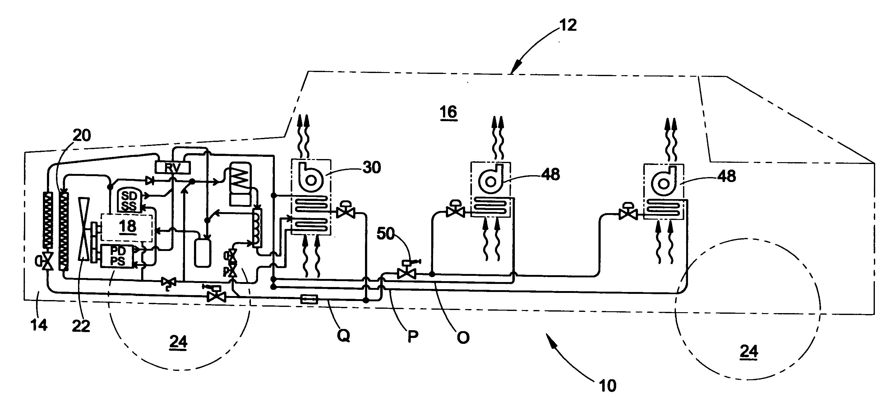
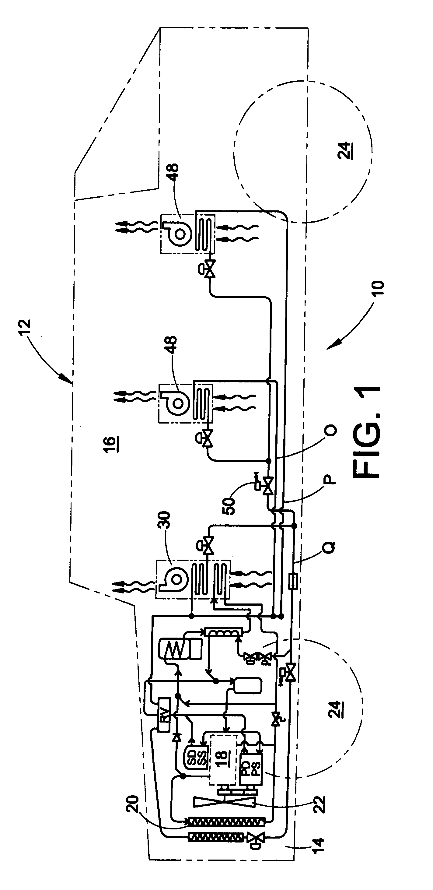
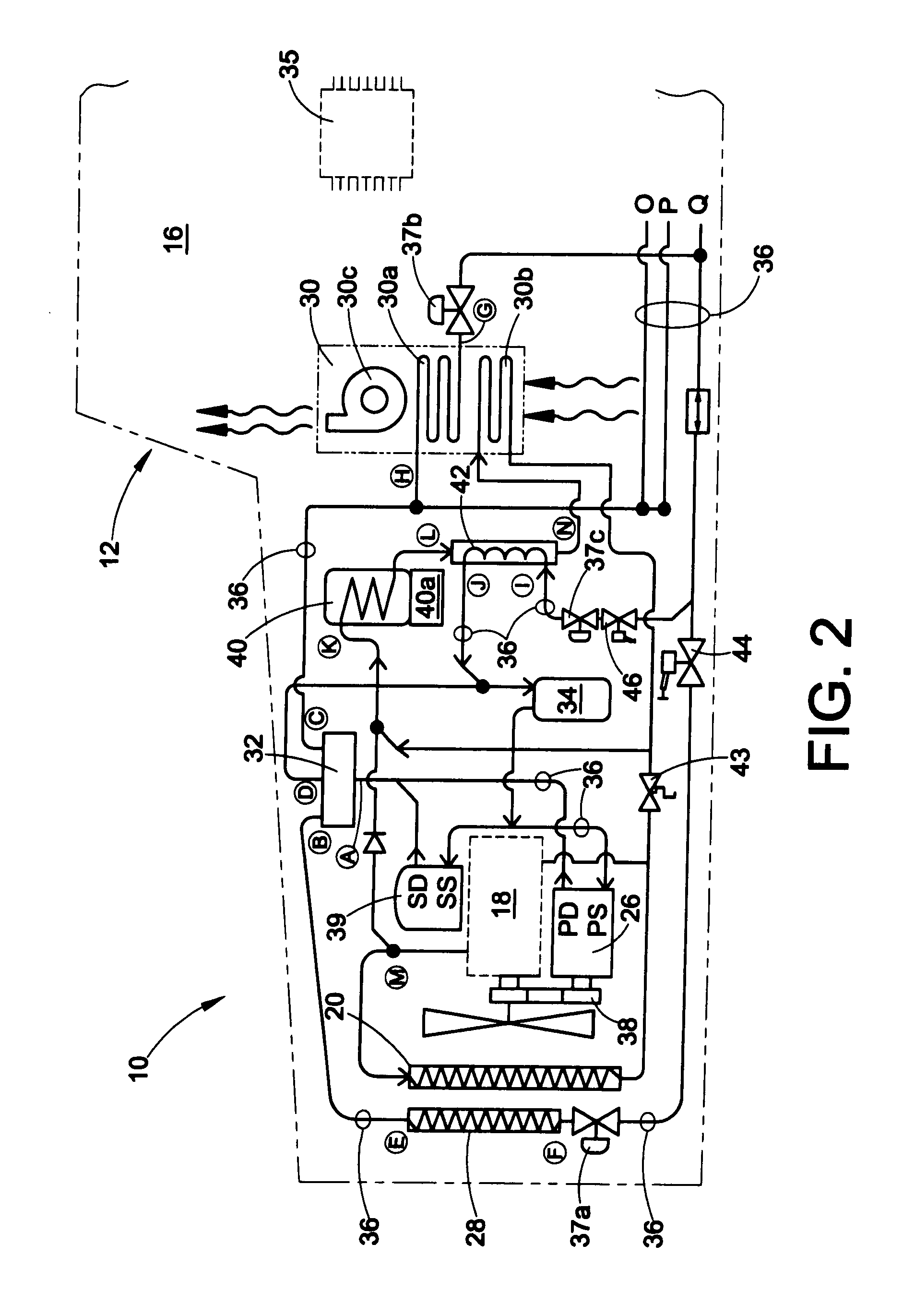
[0029]With reference to FIGS. 1 and 2, a first embodiment of a vehicle interior heating, cooling, and ventilation system (VIHCV) 10 is shown. Generally, the VIHCV system 10 is intended to be installed in a vehicle 12. The vehicle 12 may be used for the transportation of military personnel, civilians and / or cargo. In addition, the vehicle 12 may be configured as a fighting vehicle intended for tactical or combat missions. Even still, the vehicle 12 could be an electric, hybrid electric (HEV), or alternative fuel driven vehicle. Typically, the vehicle 12 includes an engine compartment 14, an interior or cabin 16, an engine or other prime mover 18, a radiator 20, a radiator fan 22 and a set of wheels 24. Also, a pressurized Nuclear, Biological, and Chemical (NBC) air filtration system 25 (FIG. 5) is supplied for collective protection providing over pressurization of the interior of the vehicle.

[0030]With reference now to FIG. 2, the VIHCV system 10 generally includes a first or primary...


PUM


Abstract

An air treatment system for a vehicle includes a first compressor selectively coupled to a first power source of the vehicle. A second compressor is selectively coupled to a second power source of the vehicle. A first heat exchanger communicating with an interior space is defined in the vehicle. A second heat exchanger communicates with an environment exterior to the vehicle. A valve member is provided which, in a first position, couples an inlet of each of the first and second compressors to an outlet of the first heat exchanger and an outlet of each of the first and second compressors to an inlet of the second heat exchanger. In a second position, the valve member couples the outlets of the first and second compressors to an inlet of the first heat exchanger and the inlets of each of the first and second compressors to an outlet of the second heat exchanger. A controller is provided that selectively actuates at least one of the first and second compressors and the valve member.

Description

FIELD OF THE INVENTION[0001]The present invention relates to the field of tactical and non-tactical vehicle cabin heating, nuclear chemical and biological (NBC) filtered and unfiltered air ventilation, and cooling systems. In particular, the present invention relates to systems intended to heat, cool, ventilate, or over pressurize the interior or crew compartment of a vehicle.BACKGROUND OF THE INVENTION[0002]The global war on terror has presented the military with new challenges. One such challenge is the redesign of combat vehicles to safely carry personnel and or cargo. One of the most important requirements for a combat vehicle's protection is counter mine design. These new mine / IED protected vehicles and armored fighting vehicles are designed for anti-personnel or larger anti-tank mines, armor penetrating and self-forged fragmented mines as well as improvised explosive devices (IEDs). To provide maximum protection new vehicles use special lower frame V shapes to deflect a mine b...

Claims


Application Information

Patent Timeline
IPC IPC(8): B60H1/00F25B1/00F25B13/00
CPCB60H1/00207F25D2400/26B60H1/00778B60H1/00907B60H1/032B60H1/3222B60H1/323B60H2001/00928B60H2001/00942F25B13/00F25B27/00F25B2313/0233F25B2327/001F25B2400/075F25B2700/2104F25B2700/2106B60H1/00414B60H1/32281
Inventor CREED, JOHN L.SKINNER, STEVEN G.
Owner HDT EXPEDITIONARY SYST
Learn More