Agricultural working machine

a working machine and working technology, applied in the field of agricultural working machines, can solve the problems of large physical effort of the person carrying out the rebuilding work, time-consuming conversion process, and high weight of the gauge wheel attachments

Inactive Publication Date: 2008-04-17
CLAAS SELBSTFAHRENDE ERNTEMASCHINEN GMBH
View PDF13 Cites 14 Cited by
  • Summary
  • Abstract
  • Description
  • Claims
  • Application Information

AI Technical Summary

Benefits of technology

[0005] The object of the invention is therefore to avoid the disadvantages of the prior art described above and, in particular, to provide a device which eliminates the need for a separate header attachm

Problems solved by technology

Such a conversion process is time-consuming and also requires major physical effort of the person carrying out the rebuildi

Method used


Image

  • Agricultural working machine
  • Agricultural working machine
  • Agricultural working machine

Examples


Embodiment Construction

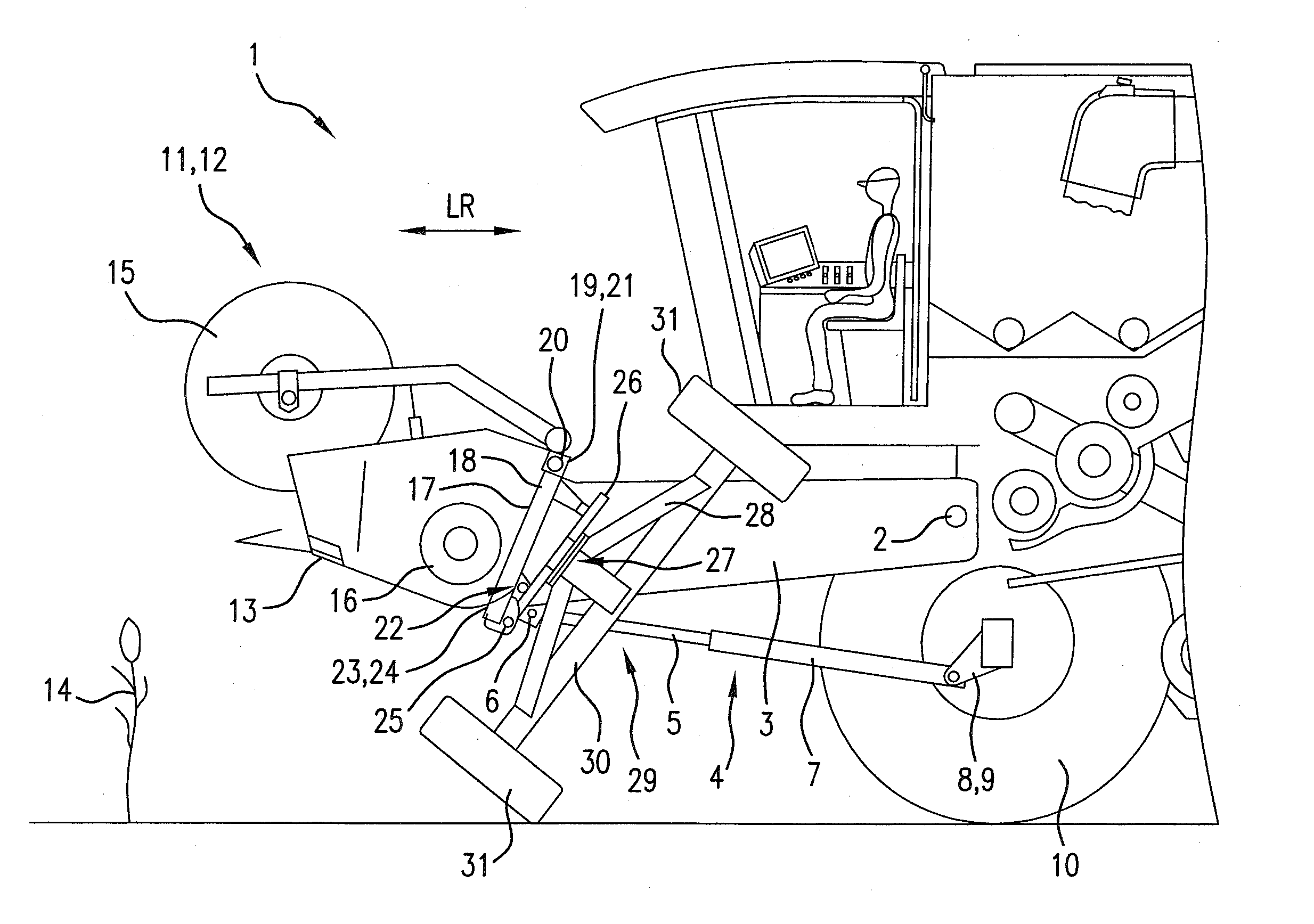
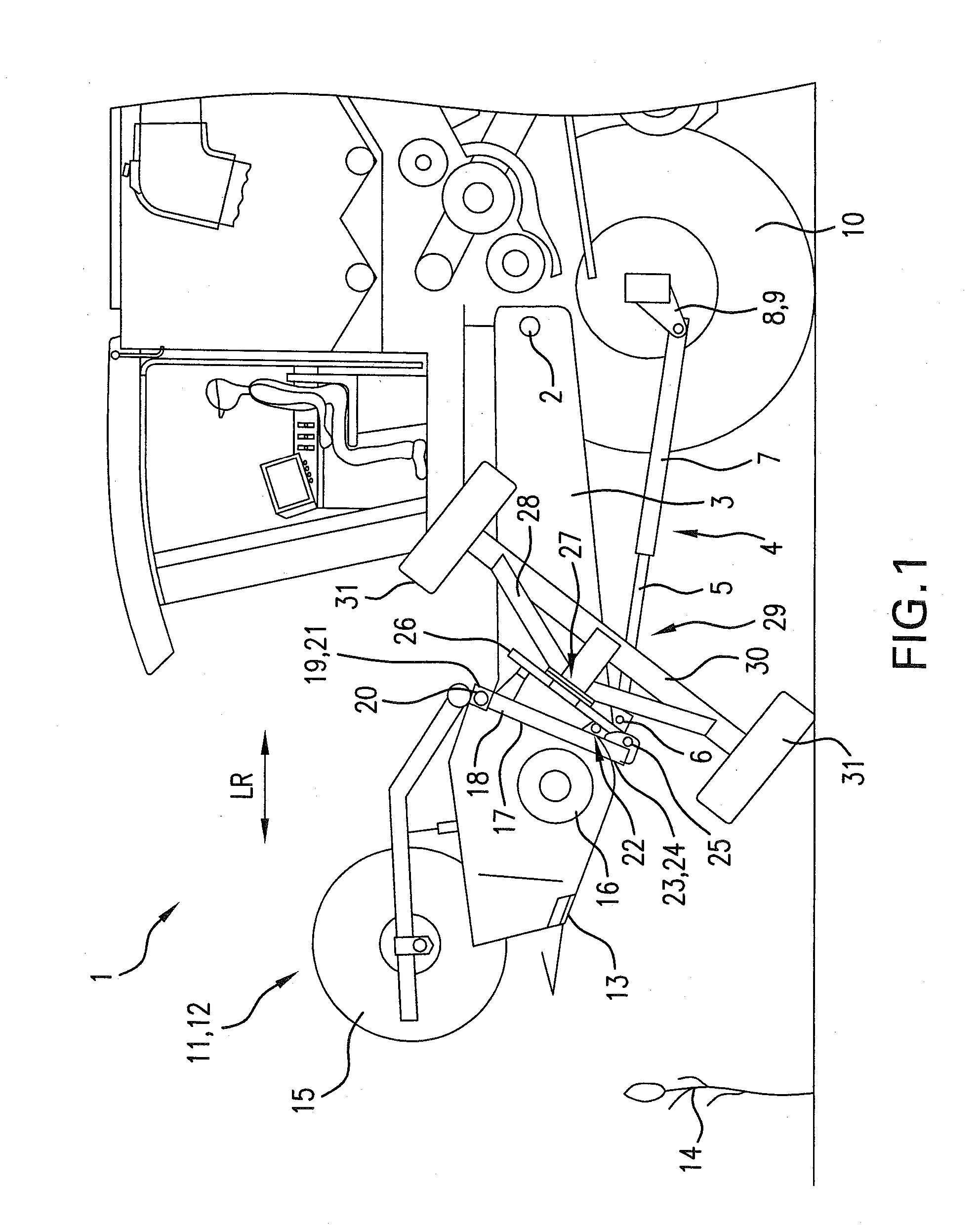
[0022]FIG. 1 shows schematically a front section of an agricultural working machine 1, which may be designed, for example, as a combine harvester, forage harvester, or a self-propelled swather. Agricultural working machine 1 accommodates in its front region a rotation axis 2 arranged transversely to its longitudinal direction LR, about which axis a so-called feeding assembly 3 can be rotated from a working position to a non-working and vice versa. According to whether agricultural working machine 1 is designed as a combine harvester or a forage harvester, this feeding assembly 3 would be designed either as a well known inclined conveyor on the combine harvester, or as a drawing-in housing on a forage harvester, also known from prior art.

[0023] The rotation of the feeding assembly 3 is generally realized by lifting cylinders 4 arranged on the bottom of the feeding assembly 3, where the piston rods 5 of these cylinders 4 bear upon retaining flanges 6 associated with feeding assembly ...


PUM


Abstract

An agricultural working machine, such as a combine harvester or forage harvester, has a feeding assembly arranged on the front for accommodating a header attachment which is designated to harvest and convey a harvested crop, and a gauge wheel attachment comprising at least support wheel associated with the header attachment on one or both sides of the feeding assembly, wherein the header attachment is arranged pivotally about a rotation axis extending transversely to the longitudinal direction of the agricultural working machine on the feeding assembly in such a manner that the header attachment can be automatically rotated from a working position into a transport position when the feeding assembly is lowered, and at least one support wheel of at least one gauge wheel attachment supports the header attachment on the ground in the transport position. This ensures that the use of a separate header trailer is not necessary. At the same time such a rotating mechanism enables support wheel arrangements to be brought quickly from a working to a non-working position without heavy physical work being required for that alteration.

Description

CROSS-REFERENCE TO A RELATED APPLICATIONS [0001] The invention described and claimed hereinbelow is also described in European Patent Applications EP 06 121 526.5 filed on Sep. 29, 2006 and EP 07 108 301.8 filed on May 16, 2007. This European Patent Applications, whose subject matter is incorporated here by reference, provide the basis for a claim of priority of invention under 35 U.S.C. 119(a)-(d). BACKGROUND OF THE INVENTION [0002] The invention relates to an agricultural working machine, such as a combine harvester or forage harvester, with a feeding assembly arranged at the front for accommodating a header attachment. [0003] An agricultural working machine of the type mentioned is disclosed in U.S. Pat. No. 5,243,810. The combine harvester disclosed there is provided with an inclined feed duct with which is associated, on the front, a crop cutting unit with a large working width. To ensure that the weight of the crop cutting unit need not be fully supported unilaterally on the g...

Claims


Application Information

Patent Timeline
IPC IPC(8): A01B73/00A01D34/00A01D75/00
CPCA01B73/005A01D75/002A01D41/14
Inventor TIPPERY, STEVESCHLUETER, MICHAEL
Owner CLAAS SELBSTFAHRENDE ERNTEMASCHINEN GMBH
Why Eureka
Try Eureka