Strain Measuring Device And Fixing Method Of Strain Measuring
- Summary
- Abstract
- Description
- Claims
- Application Information
AI Technical Summary
Benefits of technology
Problems solved by technology
Method used
Image
Examples
first embodiment
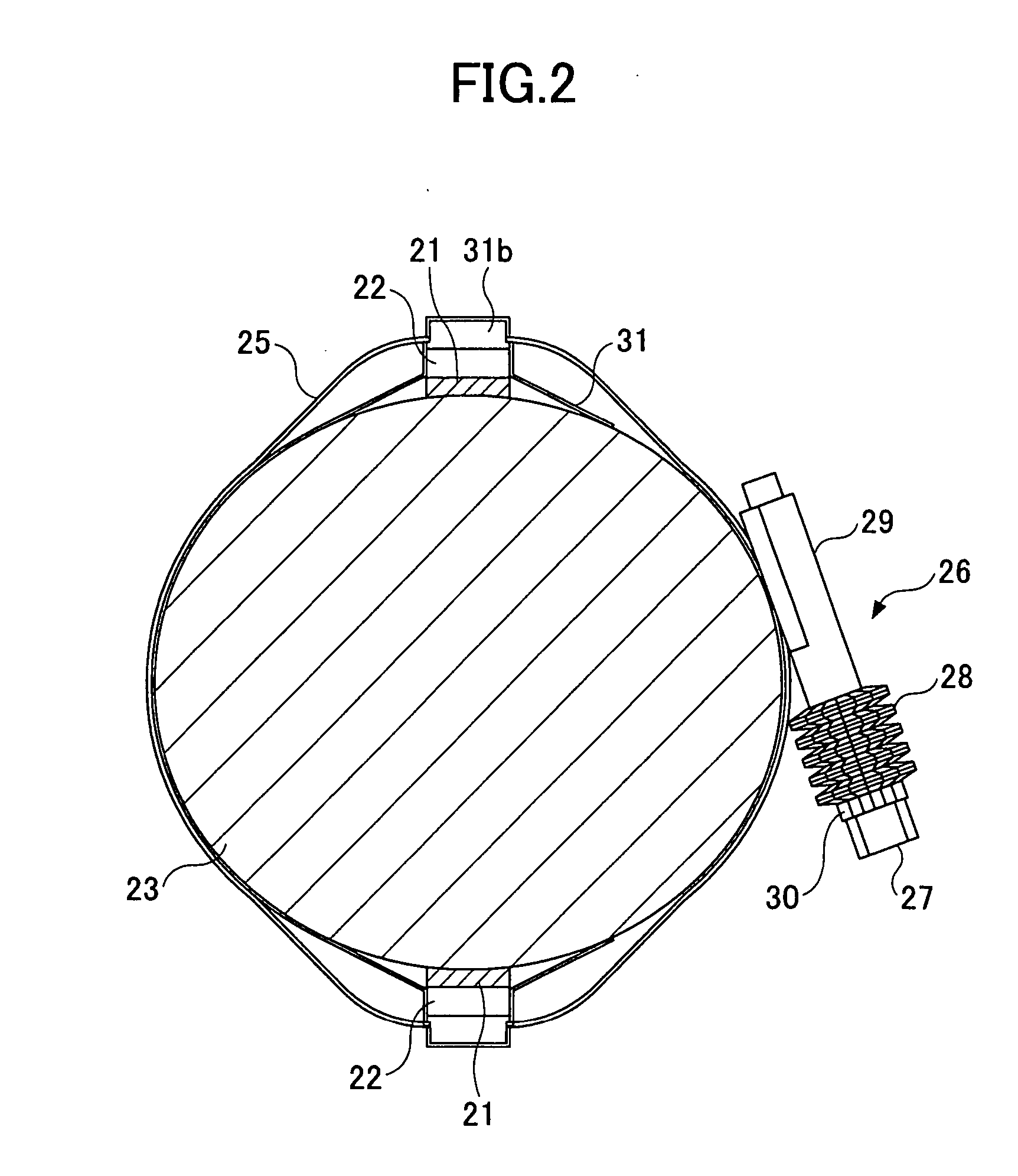
[0085] Additionally, also in the present embodiment similar to the above-mentioned first embodiment, in order to visually recognize a degree of tightening of the belt-like member 25, the scale 25b as clamping force detecting means is provided to the belt-like member 25. For example, by previously checking a position of the end of the bolt retaining member on the scale 25b at which an appropriate clamping force can be acquired, the belt-like member 25 can be tightened with an appropriate tightening force while turning the bolt 27. Additionally, by checking the clamping force by the scale 25b and further tightening the bolt 27 periodically, the appropriate clamping force (that is, the resilient restoration force of the conical plate springs 28) may be maintained. The scale 25b may include a plurality lines arranged at equal intervals, or a single line may be provided so as to be merely a measure of the initial gap distance.
[0086] The belt-like member 25 slightly slides on the outer ci...
third embodiment
[0089] The tie bar strain measuring device 40 according to the present invention has two pieces of elastic body support members 42 and two pieces of retaining members 44. The elastic body support member 42 has a fixing part 42b as a part of a body part 42a. The retaining member 44 has the same structure as the belt-like member 15 shown in FIG. 1, and is wound around the tie bar 23 via the fixing part 42b and has a function to press the fixing part 42b against the tie bar 23. That is, the retaining member 44 is a belt-like member formed in a generally circular form which matches the outer diameter of the tie bar 23, and the fixing part 42b, that is, the body part 42a can be pressed against the tie bar 23 by reducing the diameter by tightening the opposite ends by a bolt 46 and a nut 48. It should be noted that, in the present embodiment, a clamping device is constituted by the retaining members 44, the elastic body support members 42, bolts 46 and the nuts 48. In this case, since tig...
PUM
 Abstract
Description
Claims
Application Information
 - Generate Ideas
- Intellectual Property
- Life Sciences
- Materials
- Tech Scout
- Unparalleled Data Quality
- Higher Quality Content
- 60% Fewer Hallucinations
Browse by: Latest US Patents, China's latest patents, Technical Efficacy Thesaurus, Application Domain, Technology Topic, Popular Technical Reports.
© 2025 PatSnap. All rights reserved.Legal|Privacy policy|Modern Slavery Act Transparency Statement|Sitemap|About US| Contact US: help@patsnap.com


