Cleaner for the smelt spout of a recovery boiler

a technology for cleaning boilers and smelt spouts, which is applied in the direction of steam boiler components, cleaning of hollow articles, combustion process, etc., can solve the problems of danger to the personnel working and moving in the surroundings, and achieve the effect of increasing work safety

Active Publication Date: 2008-04-17
METSO POWER OY
View PDF15 Cites 8 Cited by
  • Summary
  • Abstract
  • Description
  • Claims
  • Application Information

AI Technical Summary

Benefits of technology

[0009]Now a solution for cleaning smelt spouts has been invented, which solution increases work safety.
[0017]In an embodiment the cleaning unit is suspended from the path, in which case the cleaning member of the cleaning unit is substantially placed in the area under the path. An embodiment is suspended from above in such a manner that the moving cleaning unit can travel above the floor. Thus, the structures of the cleaning apparatus do not need to be placed on the floor and the floor is free for other use. Thus, an advantage in an embodiment is the unobstructed passage to the smelt spout area. In an embodiment other structures can be placed on the floor level.
[0019]The different embodiments of the invention offer various advantages over solutions of prior art. There can be one or more of the following advantages in an application depending on its implementation.

Problems solved by technology

The possible splashes of smelt cause danger to the personnel working and moving in the surroundings.
In practice, smelt accumulates on the surfaces of the smelt spout, which smelt tends to solidify and cause plugging.

Method used


Image

  • Cleaner for the smelt spout of a recovery boiler
  • Cleaner for the smelt spout of a recovery boiler
  • Cleaner for the smelt spout of a recovery boiler

Examples


Embodiment Construction

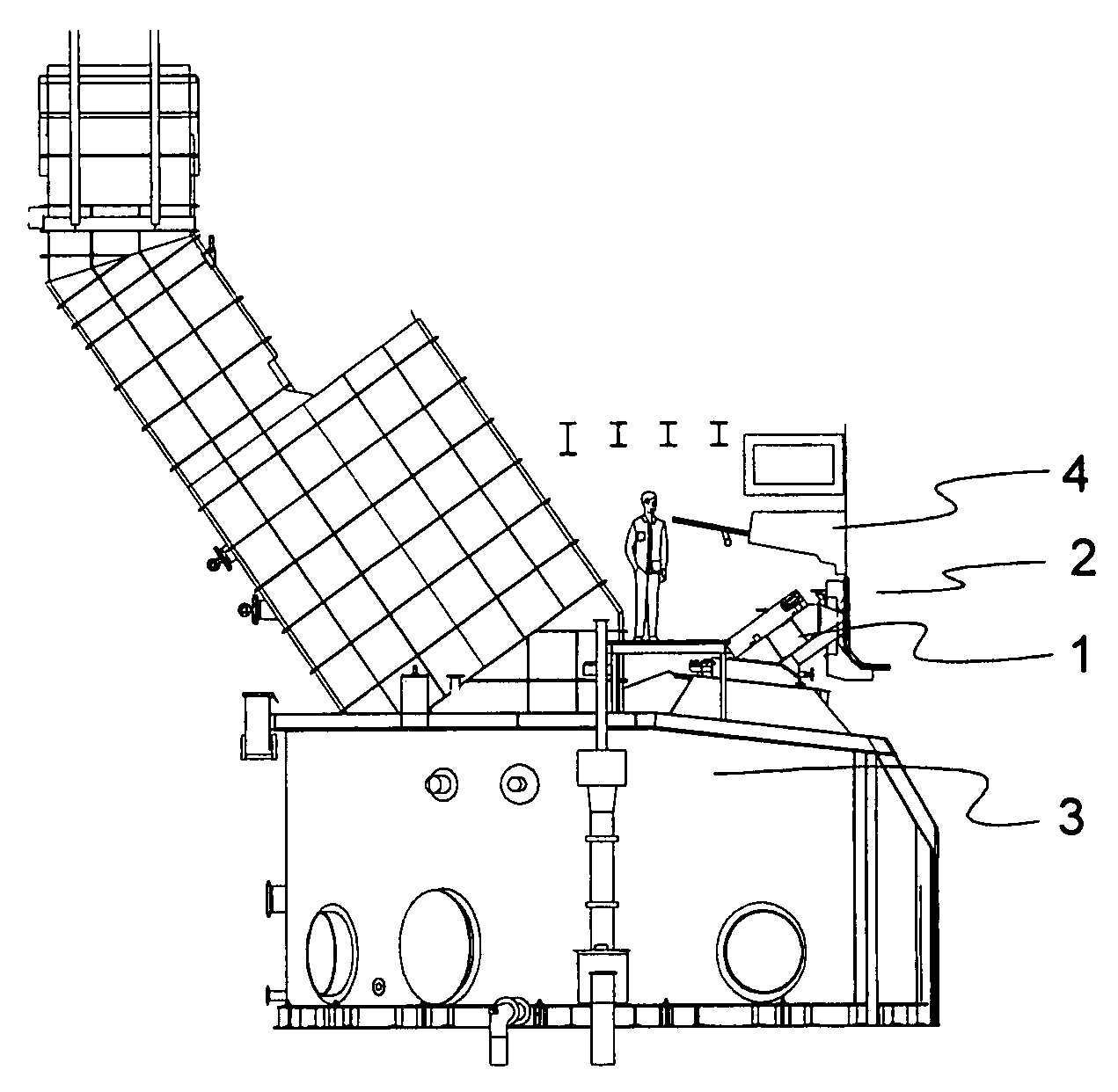
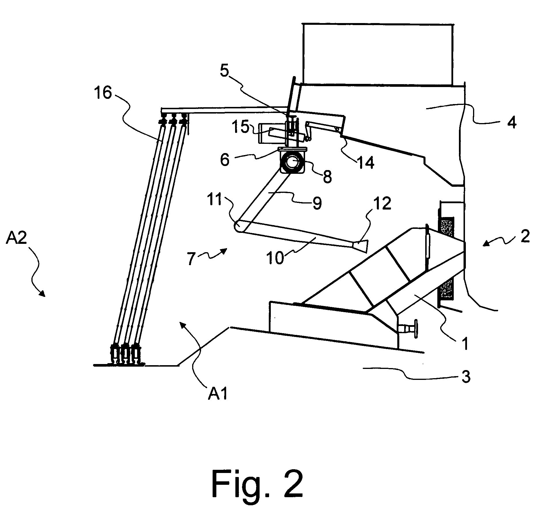
[0035]FIG. 1 shows a present smelt spout area of a recovery boiler. The area comprises smelt spouts 1, along which the smelt is directed from a furnace 2 to a dissolving tank 3. In addition, the figure shows primary air level air nozzles 4, which are placed above the smelt spouts 1.

[0036]FIG. 2 shows an embodiment of a cleaning apparatus for smelt spouts 1 of a boiler. The cleaning apparatus comprises a moving cleaning unit, a path 5 and a control unit (not shown in the figure). In the figure the path 5 is formed by a rail i.e. a guide bar connected to the wall. The cleaning unit, in turn, is formed by a carriage 6 and a cleaning member 7, which are described more in detail later in the description. The cleaning unit may travel along the path 5 horizontally parallel to the wall of the boiler. By attaching the rail 5 to the boiler wall the mutual position of the ran and the smelt spouts 1 remains substantially constant irrespective of the temperature of the wall. The dimensions of th...


PUM


Abstract

A cleaning apparatus for a smelt spout of a recovery boiler, which apparatus comprises a motorized cleaning member (7) for cleaning the smelt spout (1). The cleaning apparatus further comprises a path (5) and a cleaning unit, which comprises motorized transfer means for transferring the cleaning unit to the location of the smelt spout (1) along the path.

Description

CROSS-REFERENCE TO RELATED APPLICATIONS[0001]This application claims priority under 35 USC §119 to Finnish Patent Application No. 20065657 filed on Oct. 16, 2006[0002]1. Field of the Invention[0003]The invention relates to a cleaning unit for a smelt spout of a recovery boiler. The invention also relates to a cleaning apparatus for a smelt spout of a recovery boiler and to a method for cleaning a smelt spout of a recovery boiler.[0004]2. Background of the Invention[0005]The spent lye, i.e. the so-called black liquor created in pulp manufacture is burnt in a recovery boiler, on one hand, in order to recover the energy it includes, and on the other hand, in order to recover the chemicals in it and to recycle them back to circulation. A char bed is created on the bottom of the recovery boiler when burning black liquor, which in a high temperature forms into smelt, which is removed from the boiler as a continuous flow via smelt spouts to a dissolving tank.[0006]Below the furnace is loca...

Claims


Application Information

Patent Timeline
Patent Type & Authority Applications(United States)
IPC IPC(8): B08B9/023
CPCF23J1/08F23J1/06D21C11/12
Inventor KOSKELA, HANNUSAARELA, ARISALMI, KALLE
Owner METSO POWER OY
Why Eureka
Try Eureka