Triggerless electro-optical reader

a technology of electro-optical reader and trigger, which is applied in the direction of instruments, sensing record carriers, dynamo-electric converter control, etc., can solve the problems of consuming electrical energy, physical triggers are prone to breakage, and unsatisfactory in some respects, and achieve automatic triggering the reader, saving a great deal of electrical energy

Active Publication Date: 2008-04-17
SYMBOL TECH LLC
View PDF9 Cites 12 Cited by
  • Summary
  • Abstract
  • Description
  • Claims
  • Application Information

AI Technical Summary

Benefits of technology

[0014]In a preferred application, the reader, whether of the moving beam type or of the imaging type, is supported by the operator's hand during reading of the indicia. The reader includes a module supported on the operator's finger, and the operator points his or her finger at the indicia to be read. This application is of particular benefit to parcel delivery pe

Problems solved by technology

As advantageous as these readers are, experience has shown that they are unsatisfactory in some respects.
For example, physical triggers are prone to breakage, especially after repeated, prolonged use.
The art has proposed so-called triggerless readers that have no trigger to break, but these readers are energized all the time, thereby consuming electrical energy.
This is a problem for battery-operated readers, and especially for small form factor readers of the type supported on the operator since a smaller reader has a smaller, lighter battery that has a correspondingly smaller energy capacity.
Energy consumption is particularly high for an imaging reader since it

Method used


Image

  • Triggerless electro-optical reader
  • Triggerless electro-optical reader
  • Triggerless electro-optical reader

Examples


Embodiment Construction

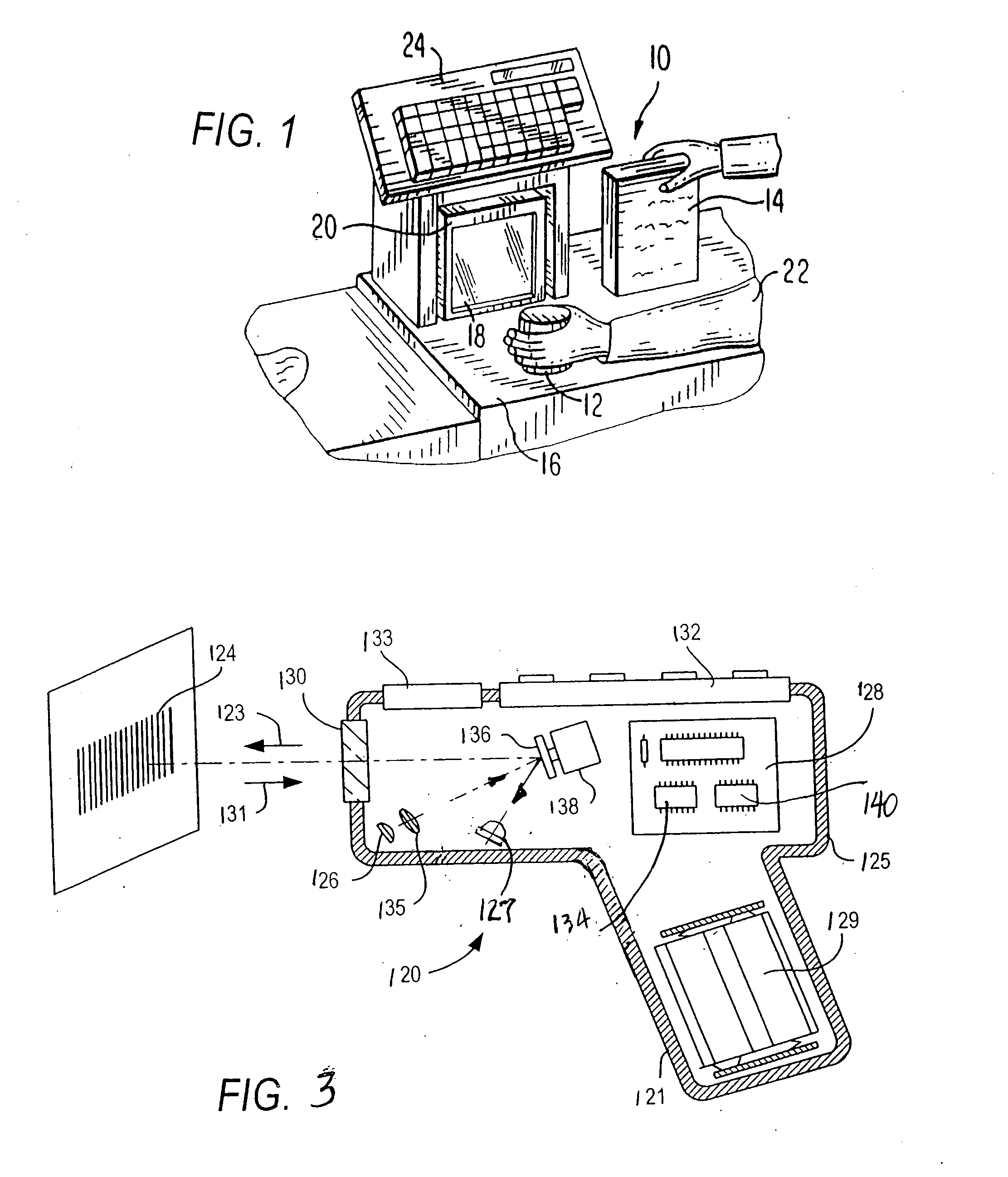
[0023]Reference numeral 10 in FIG. 1 generally identifies an electro-optical imaging reader in a workstation mode for processing transactions and mounted on a checkout counter at a retail site at which products, such as a can 12 or a box 14, each bearing a target symbol, are processed for purchase. The counter includes a countertop 16 on which a box-shaped vertical slot reader 20 having a generally vertical window 18 rests. A checkout clerk or operator 22 is located at one side of the countertop, and the reader 20 is located at the opposite side. A cash / credit register 24 is located within easy reach of the operator. In the workstation mode, the operator presents the symbols on the products to the window 18. The reader 20 is portable and lightweight and may be picked up from the countertop 16 by the operator 22 in a handheld mode, and the window 18 may be aimed at a symbol preferably on a product too heavy, or too large, or too bulky to be easily positioned on the countertop in fron...


PUM


Abstract

A software-programmed controller supported by a mobile electro-optical reader is operative for sensing when the mobile reader is supported in a steady state by the operator for a predetermined time period, and for automatically actuating the mobile reader in response to sensing the steady state to initiate reading of indicia while the mobile reader is supported in the steady state by the operator for the predetermined time period.

Description

BACKGROUND OF THE INVENTION[0001]Various electro-optical readers have previously been developed for reading bar code symbols appearing on a label, or on a surface of a target. The bar code symbol itself is a coded pattern of indicia. Generally, the readers electro-optically transform graphic indicia of the symbols into electrical signals, which are decoded into alphanumeric characters. The resulting characters describe the target and / or some characteristic of the target with which the symbol is associated. Such characters typically comprise input data to a data processing system for applications in point-of-sale processing, inventory control, article tracking and the like.[0002]Moving beam electro-optical readers have been disclosed, for example, in U.S. Pat. No. 4,251,798; U.S. Pat. No. 4,369,361; U.S. Pat. No. 4,387,297; U.S. Pat. No. 4,409,470; U.S. Pat. No. 4,760,248; and U.S. Pat. No. 4,896,026, and generally include a light source consisting of a gas laser or semiconductor las...

Claims


Application Information

Patent Timeline
IPC IPC(8): G06K7/10
CPCG06K2207/1012G06K7/10891
Inventor WANG, DAYOU
Owner SYMBOL TECH LLC
Why Eureka
Try Eureka