Methods and apparatus for hyperview automotive radar

Inactive Publication Date: 2008-04-17
CLARIANT TECH
View PDF16 Cites 65 Cited by
  • Summary
  • Abstract
  • Description
  • Claims
  • Application Information

AI Technical Summary

Benefits of technology

[0007] Methods and apparatus are presented that reduce the overall system cost for automotive radar sensing applications. In accordance with aspects of the present invention, one way sensor count reduction can be achieved is through the coverage of multiple vehicle sides through a single sensor. One embodiment combines all high-frequency signal sensor components with an antenna network which are together separately housed as an antenna unit. Each antenna unit transmits high-frequency rada

Problems solved by technology

Similarly, for vehicle applications requiring less than four quadrant

Method used


Image

  • Methods and apparatus for hyperview automotive radar
  • Methods and apparatus for hyperview automotive radar
  • Methods and apparatus for hyperview automotive radar

Examples


Example

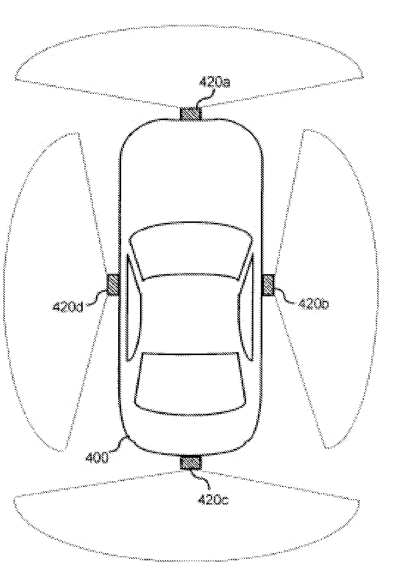
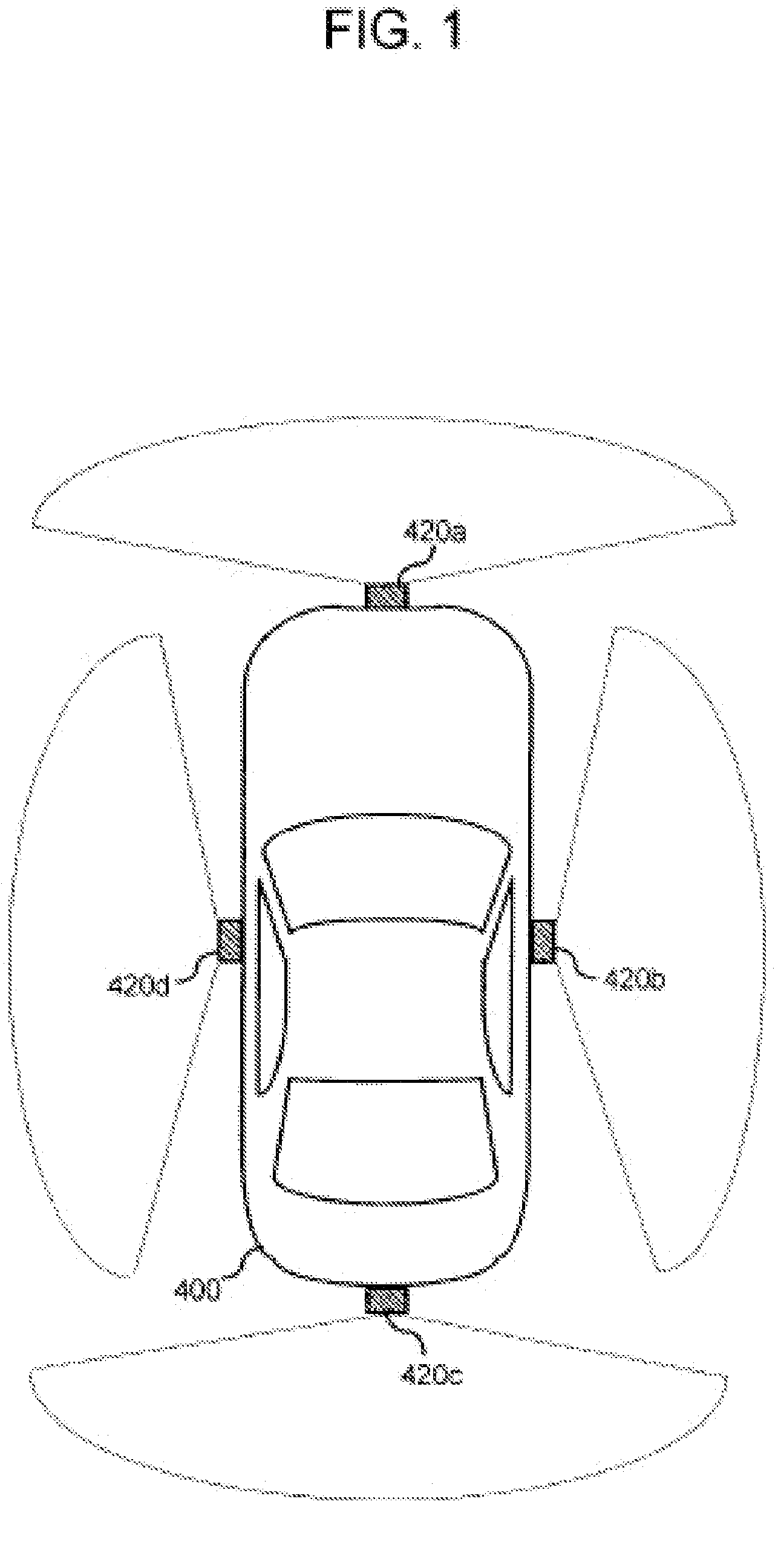
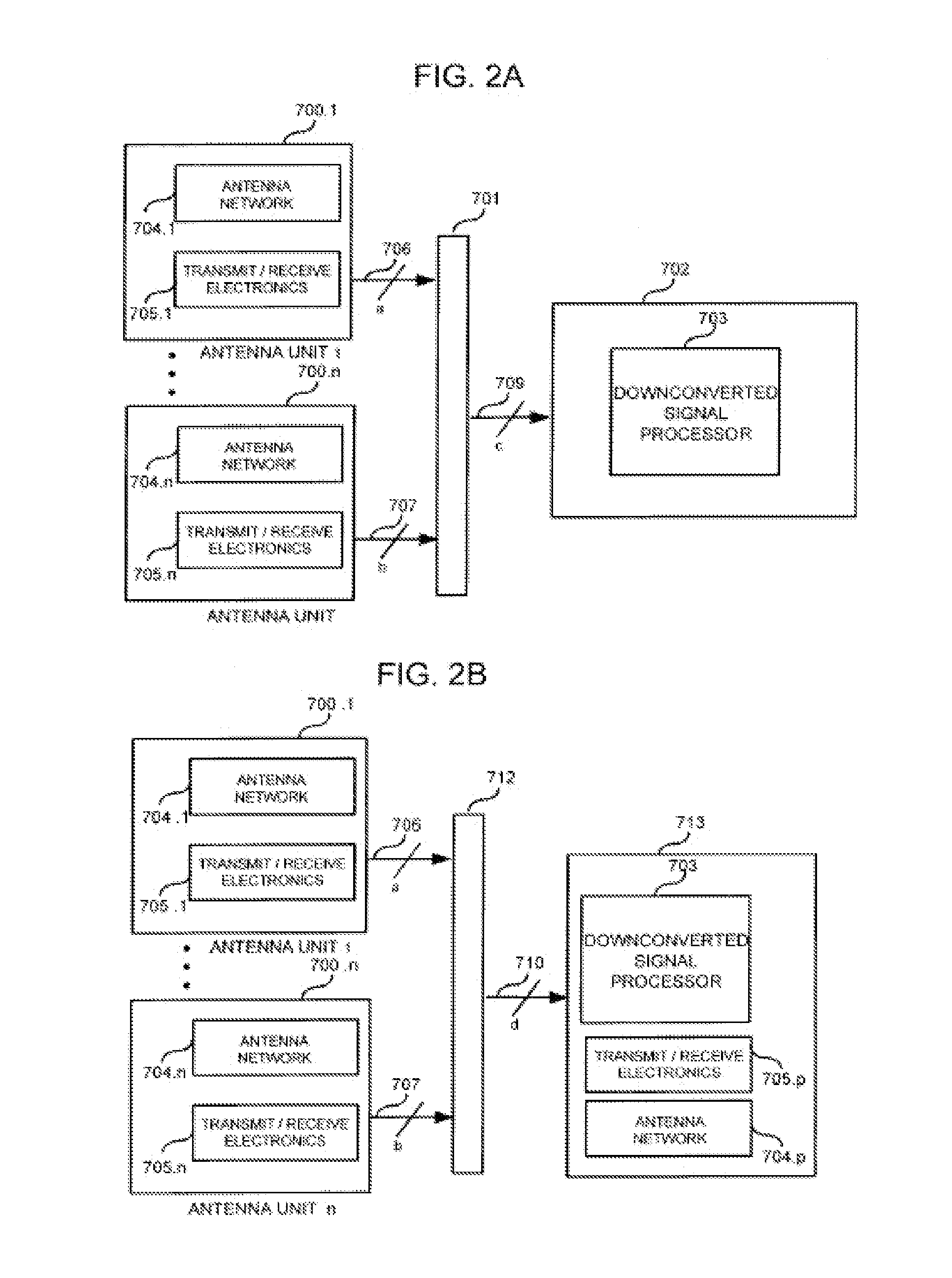
[0037]FIG. 2A illustrates an embodiment of a radar sensor according to aspects of the present invention. The radar sensor consists of a plurality of antenna units 700.1 through 700.n, a processing unit 702 and an interface means 701. In this arrangement, antenna units 700.1, 700.n each include an antenna network 704.1, 704.n for transmitting radar signals and for receiving reflected portions of said transmitted radar signal. Antenna networks 704.1, 704.n each produce one or a plurality of transmit beam shapes and one or a plurality of receive beam shapes that are utilized to implement one or a plurality of detection zones for each antenna unit 700.1, 700.n, whereby a detection zone is determined by the region of overlap between transmit and receive beams utilized for target detection. The number and types of beam shapes and detection zones may vary for different antenna units 700.1, 700.n for advantage. The total area covered by all detection regions for each antenna unit 700.1, 700...


PUM


Abstract

Methods and apparatus are presented that reduce the overall system cost for automotive radar sensing applications. In accordance with aspects of the present invention, one way sensor count reduction can be achieved is through the coverage of multiple vehicle sides through a single sensor. One embodiment combines all high-frequency signal sensor components with an antenna network which are together separately housed as an antenna unit. Each antenna unit transmits high-frequency radar signals and receives and down-converts reflected portions of said transmitted signal. The low-frequency down-converted signals produced by each antenna unit are processed through a shared processing unit which may be separately housed from all antenna units or commonly housed with an antenna unit. In addition, methods for effectively utilizing a sensor comprising multiple antenna units are described according to aspects of the present invention. Other methods and apparatus are presented.

Description

RELATED APPLICATIONS [0001] This application is related to and claims priority to U.S. Provisional Application No. 60 / 808,275, filed May 24, 2006, which is incorporated herein by reference.BACKGROUND OF THE INVENTION [0002] 1. Technical Field of the Invention [0003] The subject matter disclosed generally relates to the field of automotive electronic systems and methods. More specifically, the subject matter disclosed relates to radar sensor arrangements that allow cost reduction for automotive radar collision avoidance and driver aid applications. [0004] 2. Background of Related Art [0005] To facilitate mass deployment of automotive radar sensors, reducing the total system cost per vehicle without compromising the capability, performance, or reliability of the system is desirable. Automotive short-range sensing applications typically aim to provide a complete or nearly complete surrounding coverage around a vehicle, with target range, velocity, and angular resolution capability, and...

Claims


Application Information

Patent Timeline
IPC IPC(8): G01S13/02
CPCG01S13/931G01S2013/9332G01S2013/9385G01S2013/9378G01S2013/9375G01S2013/9315G01S2013/93271G01S2013/93272G01S2013/93274
Inventor BONTHRON, ANDREW J.JUSKOVIC, GERALD
Owner CLARIANT TECH
Why Eureka
Try Eureka