Exposure apparatus

Inactive Publication Date: 2008-04-17
CANON KK
View PDF6 Cites 14 Cited by
  • Summary
  • Abstract
  • Description
  • Claims
  • Application Information

AI Technical Summary

Benefits of technology

[0011]The present invention is directed to an exposure apparatus that provides good illuminations through a restrained distortion of the effective light source.

Problems solved by technology

The configuration of the illumination optical system disclosed in JP 2005-141158 thus remains a slight distortion in the effective light source, and cannot meet a higher imaging characteristic requirement.

Method used


Image

  • Exposure apparatus
  • Exposure apparatus
  • Exposure apparatus

Examples


first embodiment

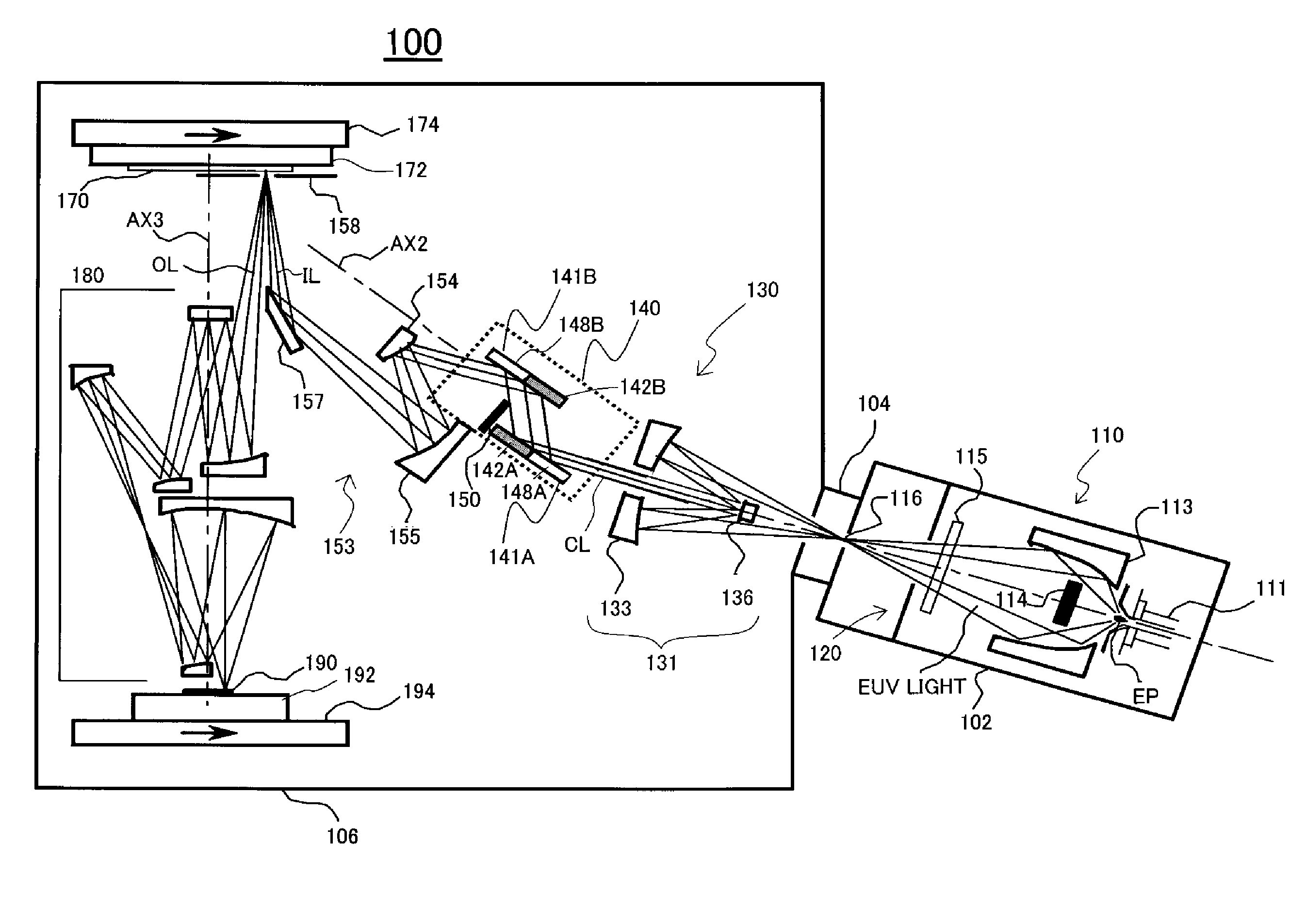
[0040]Referring now to FIG. 3, a description will be given of an exposure apparatus 100 according to a first embodiment. FIG. 3 is a schematic structural view of the exposure apparatus 100. The exposure apparatus 100 includes vacuum chambers 102 and 106, a connector 104 that connects them to each other, a light source section 110, an illumination optical system 130, a mask stage 174, a projection optical system 180, and a plate stage 194.

[0041]The vacuum chambers 102 and 106 and connector 104 accommodates components of the exposure apparatus 100, and maintain vacuum so as to prevent an attenuation of the EUV light. The vacuum chamber 102 accommodates the light source section 110. The vacuum chamber 106 accommodates the illumination optical system 130 to the plate 190.

[0042]The exposure apparatus 100 is a EUV exposure apparatus that exposes a circuit pattern of a mask 170 onto a plate 190 as a substrate using the EUV light (having a wavelength, for example, of 13.5 nm) as exposure li...

second embodiment

[0088]Referring now to FIG. 17, a description will be given of an exposure apparatus 100A according to a second embodiment of the present invention. Here, FIG. 17 is a schematic structural view of the exposure apparatus 100A. The exposure apparatus 100A has a structure similar to that of the exposure apparatus 100 except for a collimating optical system 131A, a catoptric integrator 140A, and an aperture stop 150A in the illumination optical system 130A.

[0089]The collimating optical system 131A deflects the collimated light CL by adding a plane mirror 137 to the collimating optical system 131.

[0090]The catoptric integrator 140A includes two corrugated integrator parts 143 each having plural cylindrical reflection surfaces 144A at the incident side of the aperture stop 150A. The two integrator parts 143 are arranged in a direction perpendicular to the generatrix direction G and to an arrangement direction H of the cylindrical reflection surface 144A. In addition, two integrators 143 a...


PUM


Abstract

An exposure apparatus includes a first optical unit configured to condense light from a light source, a catoptric integrator configured to form plural secondary light sources using light from the first optical unit, the catoptric integrator including plural cylindrical reflection surfaces having the same generatrix direction, an aperture stop arranged perpendicular to the generatrix direction, and a second optical unit configured to superpose light from each secondary light source onto an illumination surface, wherein the catoptric integrator includes plural integrator parts each having plural cylindrical reflection surfaces, and the plural integrator parts are arranged in a direction perpendicular to the generatrix direction and to an arrangement direction of the cylindrical reflection surfaces and located at an incident side of the aperture stop.

Description

BACKGROUND OF THE INVENTION[0001]The present invention relates to an exposure apparatus.[0002]In order to meet the recent resolution improvement requirement, a projection exposure apparatus is proposed which projects a mask pattern onto a wafer using the extreme ultraviolet (“EUV”) light having a wavelength between 10 nm and 20 nm, and is referred to as a “EUV exposure apparatus” hereinafter.[0003]A conventional illumination optical system applicable to the EUV exposure apparatus arranges an aperture stop having a semicircular aperture on a corrugated integrator for good illuminations with the small number of mirrors and no relay optical system. See, for example, Japanese Patent Laid-Open No. (“JP”) 2005-141158. The corrugated integrator is an integrator having plural cylindrical reflection surfaces having the same generatrix direction.[0004]It is known that high-quality imaging with a projection optical system requires a restrained distortion of an effective light source of the ill...

Claims


Application Information

Patent Timeline
IPC IPC(8): G03B27/72
CPCG03F7/70075G03B27/72G03F7/2008G03F7/70033G03F7/70091
Inventor KAJIYAMA, KAZUHIKOTSUJI, TOSHIHIKO
Owner CANON KK
Why Eureka
Try Eureka