Integrated thermal management of a fuel cell and a fuel cell powered device

Inactive Publication Date: 2008-04-17
MTI MICROFUEL CELLS
View PDF7 Cites 10 Cited by
  • Summary
  • Abstract
  • Description
  • Claims
  • Application Information

AI Technical Summary

Benefits of technology

[0016]Advantageously, the novel system provides integrated thermal management of an electrochemical energy conversion device and an electronic device powered by the electrochemical energy conversion device. In particular, by providing an interface between the heat-generating portions of each devi

Problems solved by technology

However, because fuel processing is complex and generally requires costly components which occupy significant volume, reformer based systems are more suitable for comparatively high power applications.
For example, if the temperature is too low, then the electrochemical reactions may not occur at a rate that provides optimum power output.
Similarly, if the temperature of the fuel cell is raised too much, the performance of the fuel cell may be compromised.
By their nature, as will be understood by those skilled in the art, today's fuel cell systems may be inefficient, producing excess heat that may adversely affect the fuel cell's operation.
Electronic devices (systems and components), including those which may be powered by electrochemical energy conversion devices (e.g., fuel cells), can become overheated, thus compromising their performance.
It is especially difficult to ef

Method used


Image

  • Integrated thermal management of a fuel cell and a fuel cell powered device
  • Integrated thermal management of a fuel cell and a fuel cell powered device
  • Integrated thermal management of a fuel cell and a fuel cell powered device

Examples


Embodiment Construction

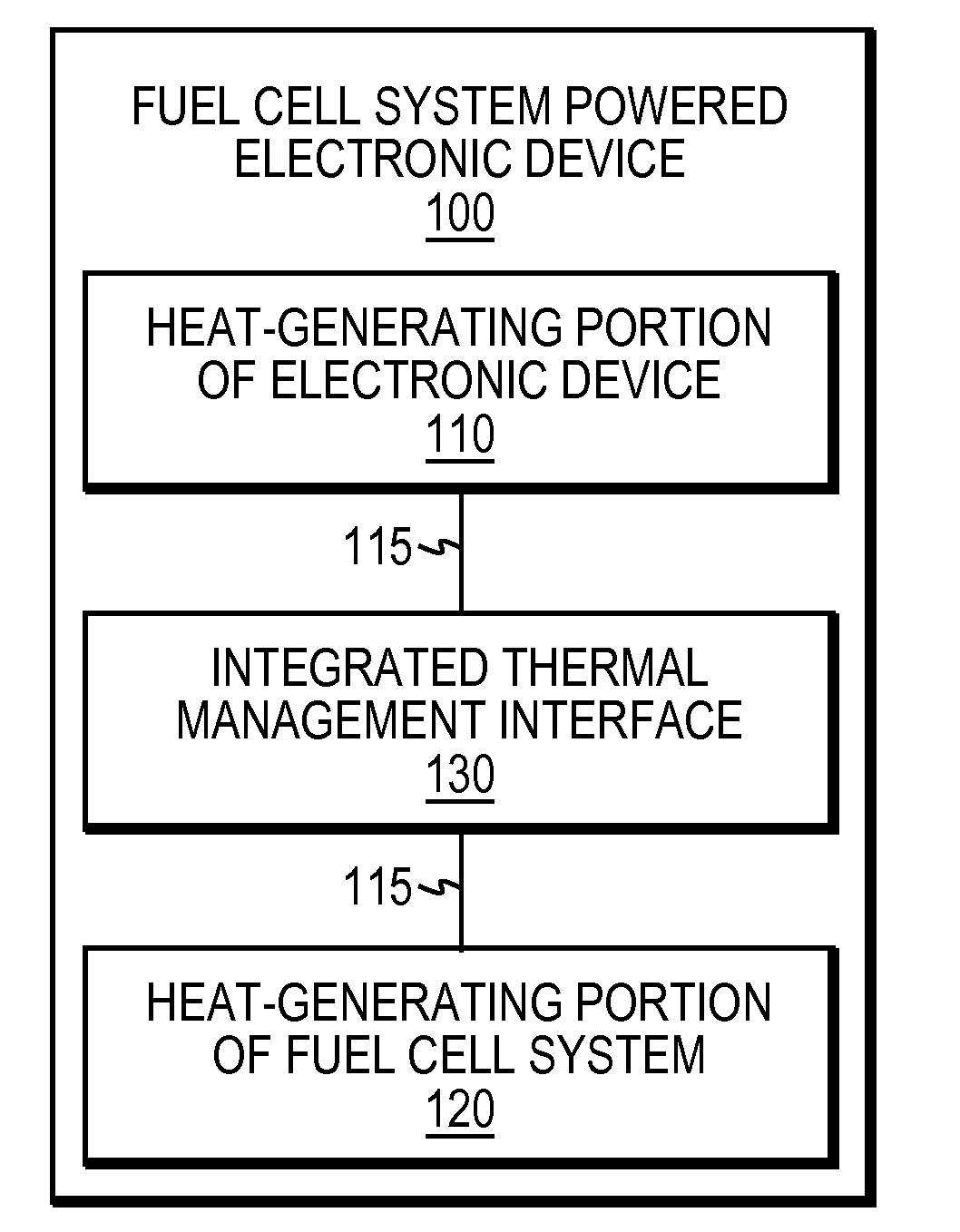
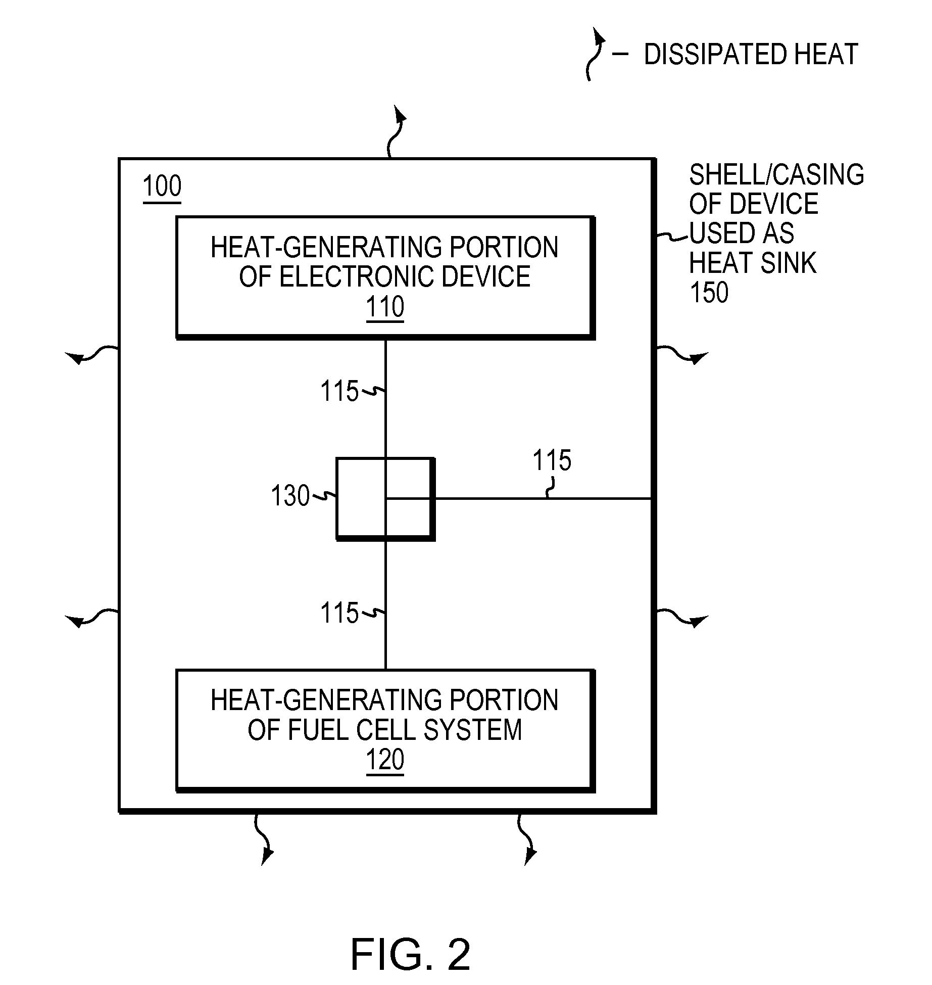
[0022]FIG. 1 is a simplified schematic block diagram of one embodiment of an electronic device 100 that may be powered by an electrochemical energy conversion device and advantageously used with the present invention. As will be understood by those skilled in the art, the electronic device may have a heat-generating portion 110, such as, e.g., from various processors, power converters, visual displays, or other components that may generate heat during their operation.

[0023]Illustratively, the electrochemical energy conversion device (and heat-generating portion thereof) 120 is a fuel cell system, e.g., a direct oxidation fuel cell, direct methanol fuel cell (DMFC), liquid or vapor feed fuel cell, portable fuel cell, transportable reformer-based fuel cell system, or other electrochemical energy conversion device (including other forms of fuel cells), as will be understood by those skilled in the art.

[0024]Notably, there are many different electrochemical energy conversion devices tha...


PUM


Abstract

An integrated thermal management of an electrochemical energy conversion device (e.g., a fuel cell) and an electronic device powered by the electrochemical energy conversion device is described. According to the present invention, an integrated thermal management interface may be used to intentionally manage and control the heat generated by both devices in a shared and efficient manner (e.g., in addition to natural heat dissipation). In particular, the interface may be a unified sub-system, which may be electrical or mechanical (or a combination of both), used to actively control the heat of the two distinct devices, i.e., the heat-generating portions of the two devices, by creating a thermally conductive path to a shared heat dissipation mechanism. In accordance with aspects of the present invention, the interface may be embodied as one or more shared thermally conductive paths, fans, air pumps, heat sinks, switches, etc.

Description

CROSS REFERENCE TO RELATED APPLICATIONS[0001]The present invention is related to commonly owned copending U.S. patent application Ser. No. 11 / 021,971 for an APPARATUS AND METHOD FOR VARIABLE CONDUCTANCE TEMPERATURE CONTROL, filed by Becerra et al. on Dec. 23, 2004, the contents of which are hereby incorporated by reference in its entirety.BACKGROUND OF THE INVENTION[0002]1. Field of the Invention[0003]This invention relates generally to electrochemical energy conversion devices (e.g., a fuel cell) and electronic devices powered by the electrochemical energy conversion devices, and, more particularly, to integrated thermal management of the devices.[0004]2. Background Information[0005]Electrochemical energy conversion devices, generally, are devices that convert one or more chemicals into energy (i.e., electricity) through one or more chemical reactions. In particular, fuel cells are an example of such a device in which electrochemical reactions are used to generate electricity from ...

Claims


Application Information

Patent Timeline
IPC IPC(8): H01M14/00
CPCH01M8/04007H01M8/0432H01M8/04738F28F2013/008H01M8/1011Y02E60/523H01M8/04768Y02E60/50
Inventor SCARTOZZI, JOHN PERRYPRUEITT, JAMES K.MODI, ASHISH K.CARLSTROM, CHARLES M.
Owner MTI MICROFUEL CELLS
Why Eureka
Try Eureka