Roof truss

Inactive Publication Date: 2008-04-24
PERRAULT LARRY +1
View PDF51 Cites 5 Cited by
  • Summary
  • Abstract
  • Description
  • Claims
  • Application Information

AI Technical Summary

Benefits of technology

[0009] This invention is an improvement on roof trusses. It reduces cracking between the ceiling finish and the interior partition wall finish caused by arching of the roof trusses. This is accomplished by means of a bottom plate which is attached to a top plat

Problems solved by technology

This temperature differential can cause different contraction and expansion of the various parts of the roof truss, resulting in vertical deflection of the roof truss.
Therefore, if there is vertical arching of the trusses, the ceiling finish is lifted by the bottom chords, and cracks develop between the interior wall finish and the ceiling finish.
Cracking caused by ve

Method used


Image

  • Roof truss
  • Roof truss
  • Roof truss

Examples


Example

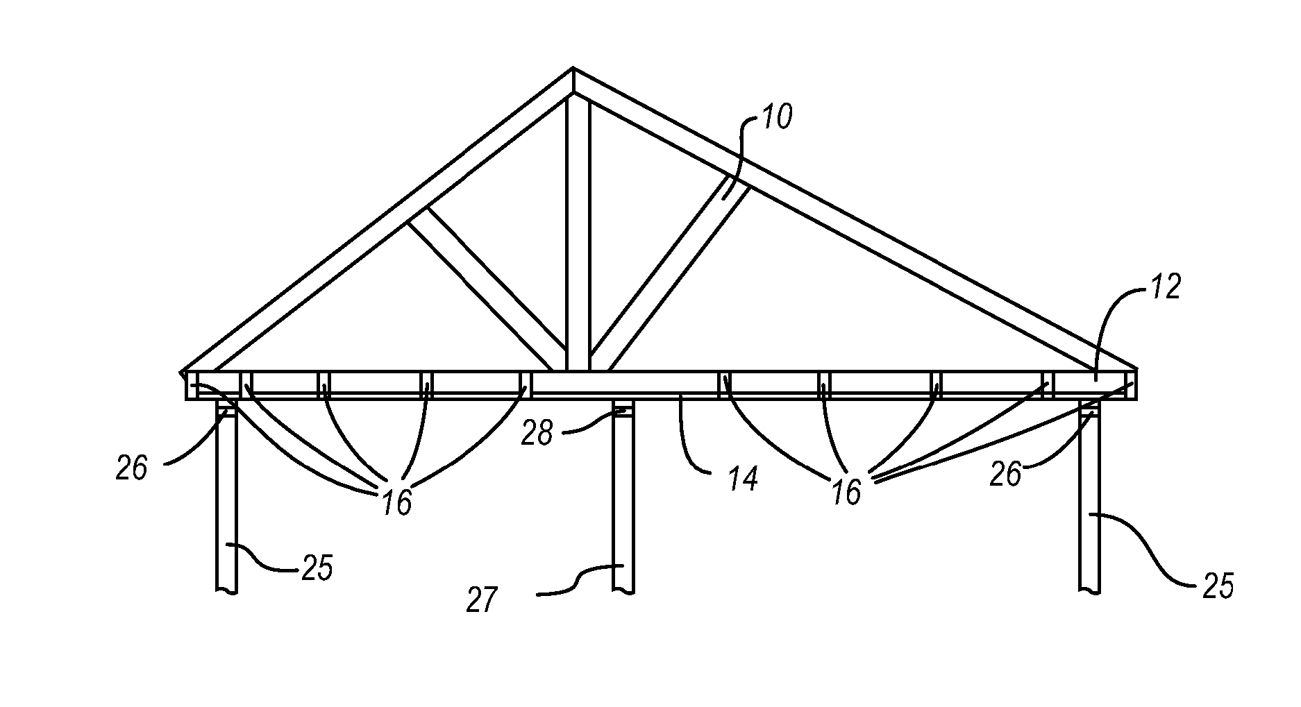
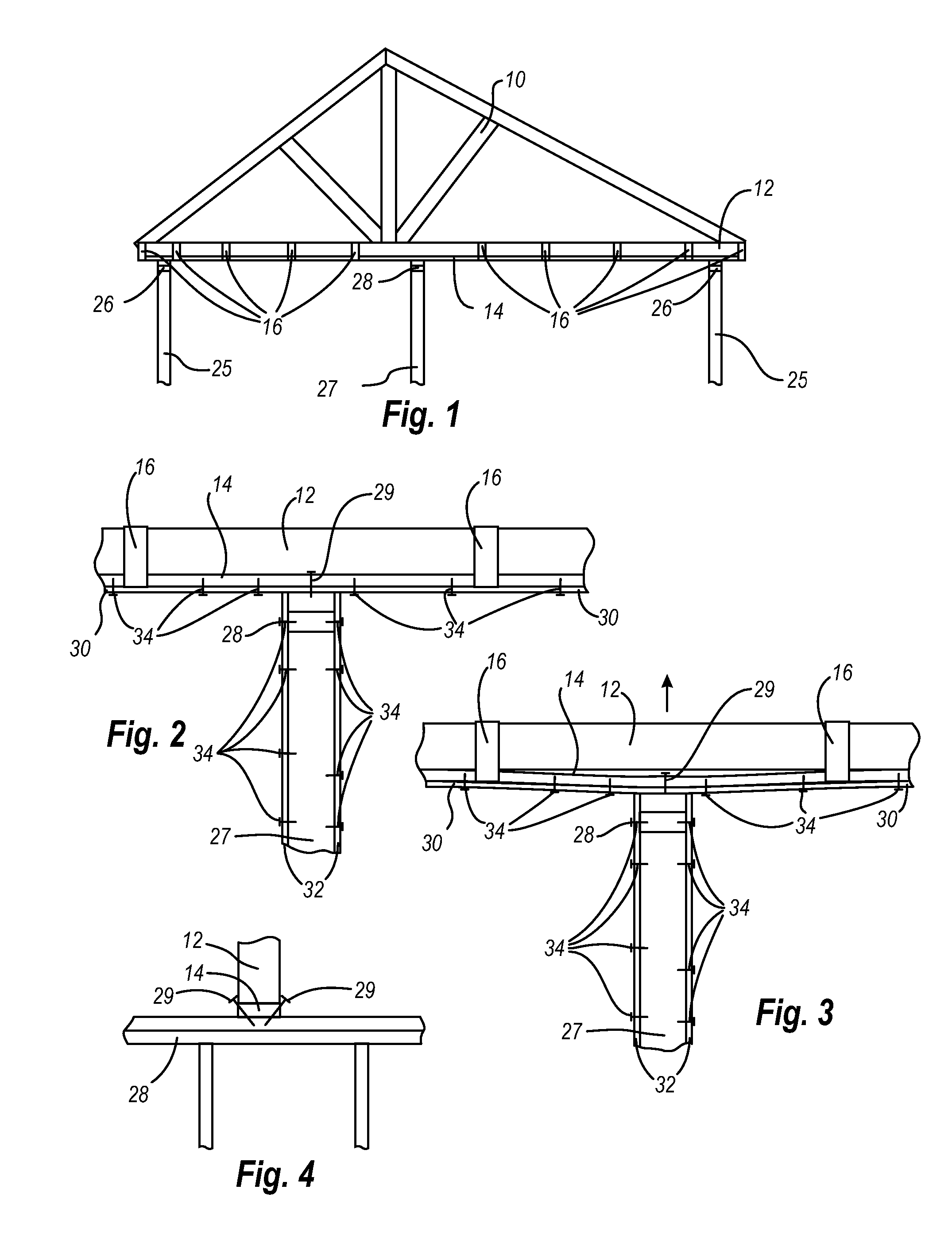
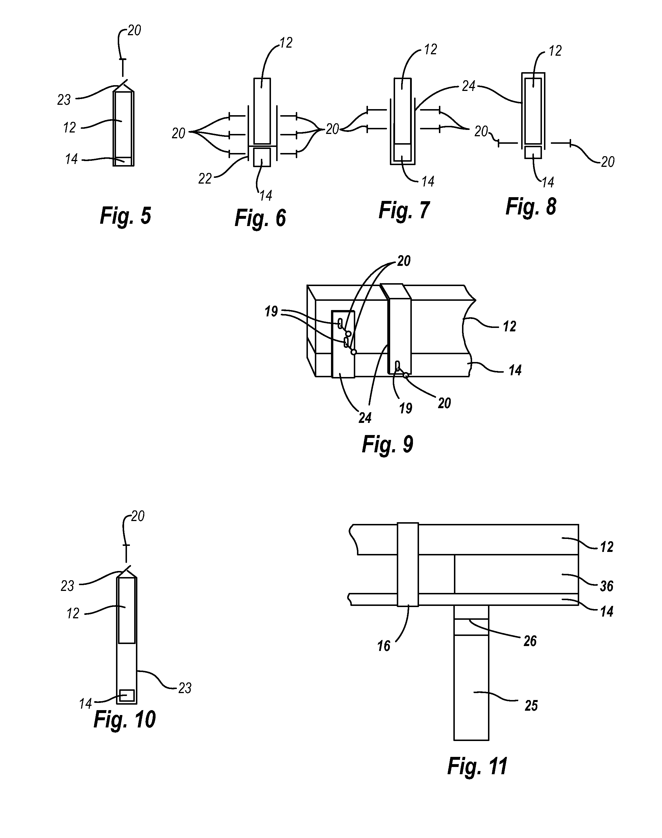
[0026] The present invention provides for an improved roof truss. The invention according to the Figures comprises a roof truss (10) wherein a bottom plate (14) is attached to the bottom chord (12) of the roof truss (10) by a plurality of connectors (16).

[0027] The bottom plate (14) may be wood, a wood composite, or any other appropriate material. In one embodiment the bottom plate is ¾ inch oriented strand board. In use, the bottom plate is attached to the top plate of the interior partition walls, typically by way of nails, screws, brackets, straps or other appropriate fasteners.

[0028] The bottom plate (14) may be attached to the roof truss in many ways. Typically, the bottom plate is suspended from the underside of the bottom chord (12) of the roof truss (10) by a plurality of appropriate connectors (16). The connectors attaching the bottom plate to the bottom chord permit the bottom plate and the ceiling finish to flex to accommodate some vertical movement of the bottom chord....


PUM


Abstract

A prefabricated roof truss which includes a bottom plate which attaches to the bottom chord of the roof truss in such a way that the bottom plate does not lift away from the top plate of an interior wall despite the vertical movement of the bottom chord of the roof truss.

Description

CROSS-REFERENCE TO RELATED APPLICATIONS [0001] This application is a continuation of application Ser. No. 09 / 713,296, filed Nov. 16, 2000, which is pending and incorporated herein by this reference.FIELD OF THE INVENTION [0002] The present invention provides for an improved roof truss. BACKGROUND OF THE INVENTION [0003] Prefabricated roof truss systems have been used in construction for a number of years. Roof trusses can be made from wood, wood composites, metal and other materials. [0004] In some situations, vertical arching or deflection of the roof truss occurs. The vertical arching of trusses appears to result from a difference in the temperature that the top and bottom chords are subjected to. In climates where it is necessary to insulate the building for efficient heating or cooling, the ceiling is generally insulated by placing the insulating material between and upon the bottom chords of the roof truss. Therefore the bottom chords are at least partially insulated and can be...

Claims


Application Information

Patent Timeline
IPC IPC(8): E04C3/18E04B1/49E04C3/29F16B5/12E04B9/00E04C3/02E04C3/17
CPCE04B9/00E04C2003/026E04C3/17
Inventor PERRAULT, LARRYKARROLL, DAVID R.
Owner PERRAULT LARRY
Why Eureka
Try Eureka