Plasma cutting device, plasma torch, and cooling device for plasma torch

a cutting device and plasma torch technology, applied in plasma torch, manufacturing tools, welding apparatus, etc., can solve the problems of increasing the cooling water flow rate, increasing the difficulty of exchanging the electrode or the nozzle, and large pressure loss within the electrode, so as to enhance the durability of the nozzle, simple and easy manner, and simple and easy manner

Active Publication Date: 2008-04-24
KOMATSU LTD +1
View PDF10 Cites 38 Cited by
  • Summary
  • Abstract
  • Description
  • Claims
  • Application Information

AI Technical Summary

Benefits of technology

[0019]In a preferred embodiment, the electrode coolant liquid passage and the nozzle coolant liquid passage of the plasma torch have separate and different inlets, the coolant liquid supply device includes a first coolant liquid outlet and a second coolant liquid outlet which is separate from the first coolant liquid outlet, and the first coolant liquid outlet and the inlet of the electrode coolant liquid passage are connected together by an electrode coolant liquid supply conduit, while the second coolant liquid outlet and the inlet of the nozzle coolant liquid passage are connected together by a nozzle coolant liquid supply conduit which is separate from the electrode coolant liquid supply conduit. By driving the electrode coolant liquid supply conduit for supplying coolant liquid to the electrode and the nozzle coolant liquid supply conduit for supplying coolant liquid to the nozzle separately in this manner, not only within the plasma torch, but exterior to the plasma torch as well, it is possible to supply coolant liquid to the electrode and to the nozzle, in individual characteristic flow rates adapted to their individual cooling requirements, in a yet simpler and easier manner.
[0020]Furthermore, in the embodiment described above, the coolant liquid discharge device discharges a first flow of coolant liquid for cooling the electrode from the first coolant liquid outlet and discharges a second flow of coolant liquid for cooling the nozzle from the second coolant liquid outlet, and sets or controls the flow rate of the first flow of coolant liquid and the flow rate of the second flow of coolant liquid separately. By thus setting or controlling the flow rate of the first flow of coolant liquid which is supplied to the electrode and the flow rate of the second flow of coolant liquid which is supplied to the nozzle separately, it is possible to supply coolant liquid to the electrode...

Problems solved by technology

Due to this, the pressure loss within the electrode is large.
However, since the influence of attrition of the nozzle due to heat is directly manifested in deterioration of cutting quality, accordingly, in order to suppress such deterioration, there is a strong demand for increase of the cooling water flow rate suppl...

Method used


Image

  • Plasma cutting device, plasma torch, and cooling device for plasma torch
  • Plasma cutting device, plasma torch, and cooling device for plasma torch
  • Plasma cutting device, plasma torch, and cooling device for plasma torch

Examples


Embodiment Construction

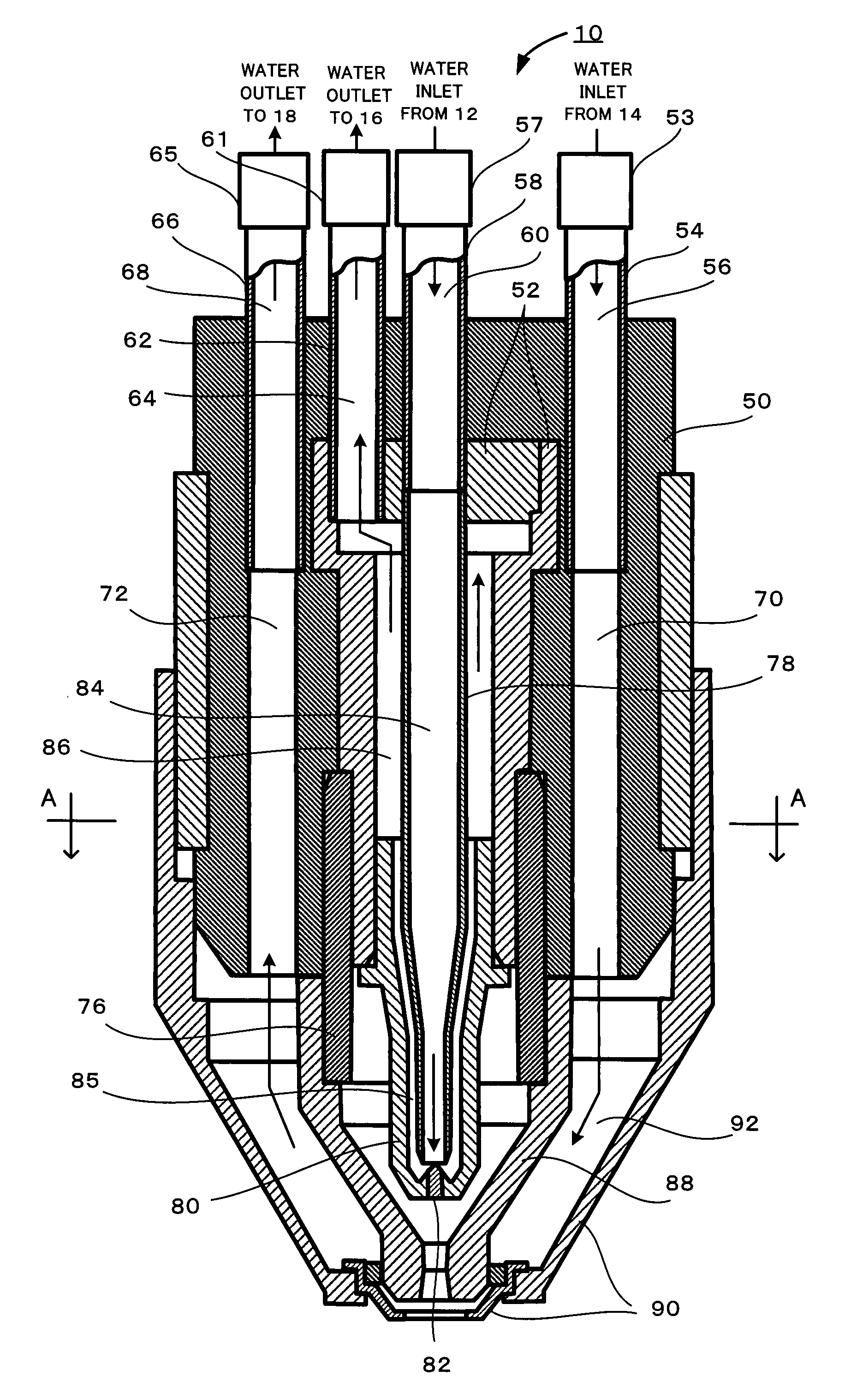
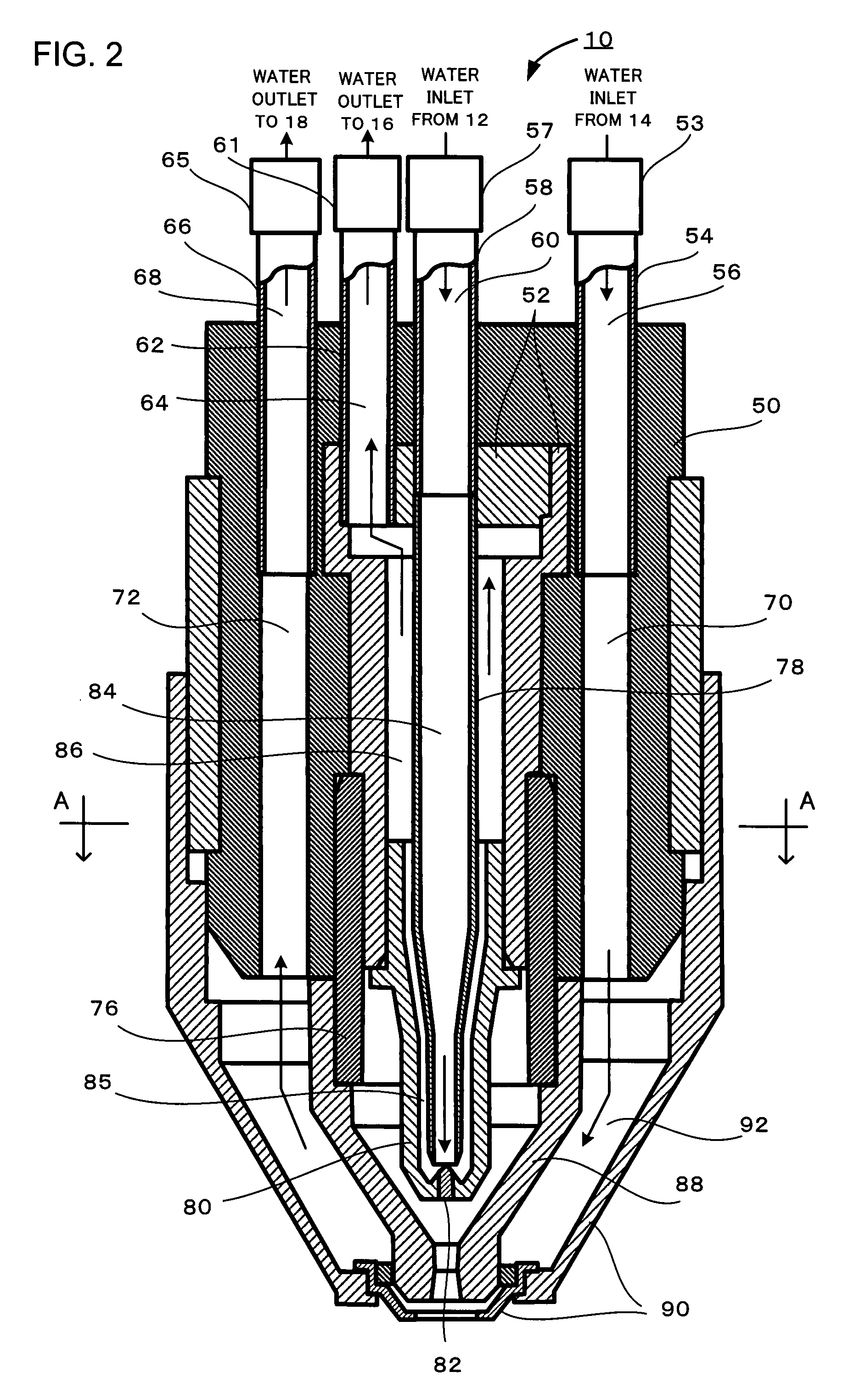
[0031]A plasma cutting device according to an embodiment of the present invention will now be explained. This plasma cutting device is a device which cuts a workpiece using a plasma torch. This plasma torch comprises a removable electrode and a nozzle; the electrode serves the role of generating a plasma arc, while the nozzle serves the role of squeezing down the plasma arc and directing it towards the workpiece. In the following, explanation of this plasma cutting device according to an embodiment of the present invention will concentrate in particular upon the portions thereof which are related to cooling of the plasma torch, and this explanation will make reference to the drawings.

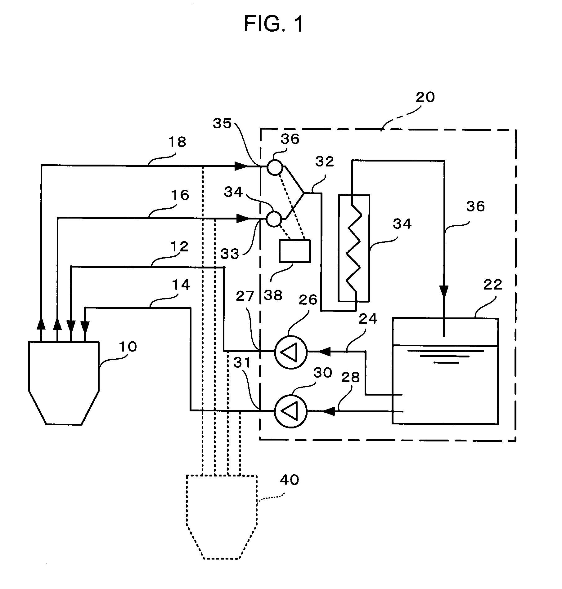
[0032]FIG. 1 shows a liquid cooling circuit for supplying a coolant liquid—for example, in this embodiment, water (hereinafter termed “cooling water”)—to the plasma torch of the plasma cutting device according to this embodiment of the present invention. Here, although the portion of this liquid cooling...


PUM

PropertyMeasurementUnit
Flow rateaaaaaaaaaa

Abstract

In order to increase the flow rate of coolant liquid supplied to the nozzle (88) of a plasma torch (10) and to extend the life of the plasma torch (10), within the plasma torch (10), an electrode coolant liquid passage (60, 84, 85, 86, and 64 which supplies coolant liquid to an electrode (80), and a nozzle coolant liquid passage (56, 70, 92, 72 and 68) which supplies coolant liquid to the nozzle (88), are provided separately as independent coolant liquid passages which extend in parallel, and which are mutually electrically insulated from one another. Moreover, the flow rate of coolant liquid in the nozzle coolant liquid passage is greater than the flow rate of coolant liquid in the electrode coolant liquid passage.

Description

TECHNICAL FIELD[0001]The present invention relates to a plasma cutting device, to a plasma torch, and to a cooling device for a plasma torch, and in particular relates to improvement in technique for cooling a plasma torch.BACKGROUND ART[0002]The electrode and nozzle of a plasma torch are directly exposed to a high temperature plasma arc. In order to prevent attrition of the electrode and the nozzle due to this high temperature, normally, cooling water is flowed through the interior of the electrode and around the exterior of the nozzle, so that the electrode and the nozzle are cooled (refer to Patent Document #1). Generally, this cooling water is fed under pressure to the torch by a pump from a water tank of a cooler unit which is installed exterior to the plasma cutting device. Within the torch, this cooling water first passes through the base end portion of the torch and enters into a water passage internal to the electrode and cools the electrode, and thereafter enters into a wa...

Claims


Application Information

Patent Timeline
IPC IPC(8): H05H1/28B23K9/24
CPCH05H1/34H05H2001/3457H05H1/28H05H2001/3484H05H2001/3442H05H1/3442H05H1/3457H05H1/3484
Inventor YAMAGUCHI, YOSHIHIROMORIMOTO, SHIGEOMINONISHI, MIKIO
Owner KOMATSU LTD
Why Eureka
Try Eureka