
Voltage regulator with output accelerated recovery circuit

a voltage regulator and output technology, applied in the direction of electric variable regulation, process and machine control, instruments, etc., can solve the problems of output load current changing more rapidly than the amplifier can respond, reference voltage vsub>g /sub>can not reflect the variation of vsub>out /sub>rapidly enough

Inactive Publication Date: 2008-04-24
HOLTEK SEMICON
View PDF4 Cites 27 Cited by
  • Summary
  • Abstract
  • Description
  • Claims
  • Application Information

AI Technical Summary

Benefits of technology

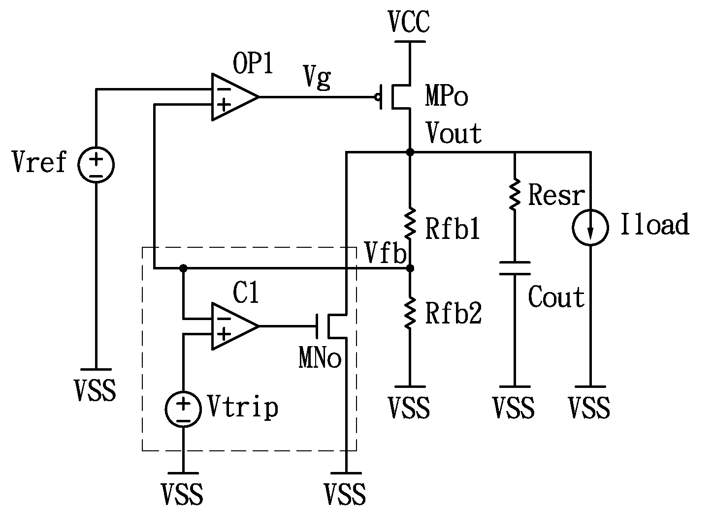
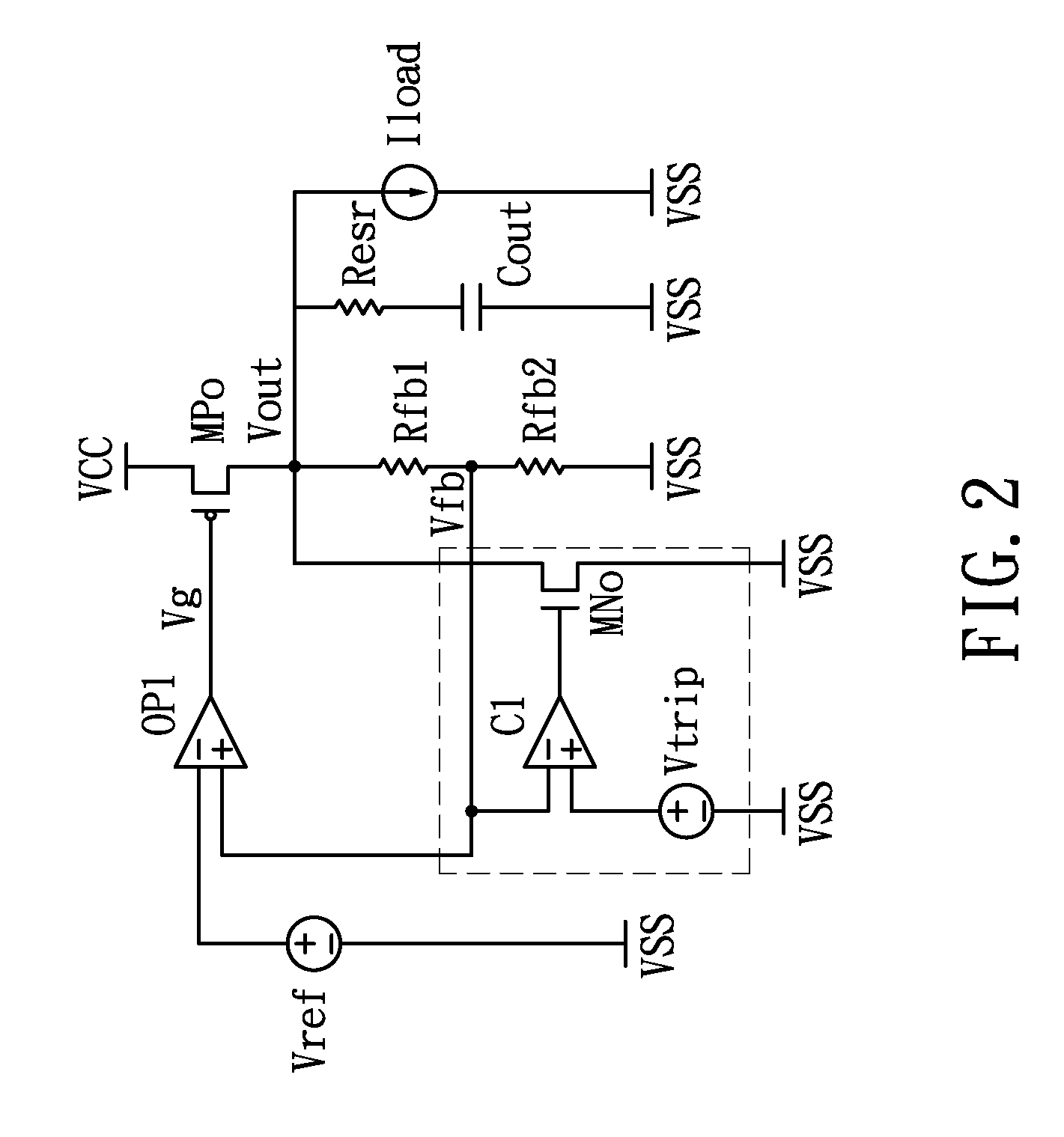
[0004]In view of the disadvantages of prior art, the primary object of the present invention is to provide an improved voltage regulator achieved by configuring additionally a comparator and a pull-down transistor into a low dropout voltage regulator (LDO), both being connected between the positive feedback input node of its operational amplifier (OP) and the ground end thereof; wherein the comparator is used for detecting the voltage variation of a reference node while the reference node is defined to be a node located between a first feedback resistor and a second feedback resistor so that the voltage of the positive feedback input node can be detected thereby; and the pull-down transistor is forced to turn on so as to sink the output voltage (Vout) rapidly for returning the same back into regulation as the voltage detected at the reference node is larger than a predetermined voltage.

Problems solved by technology

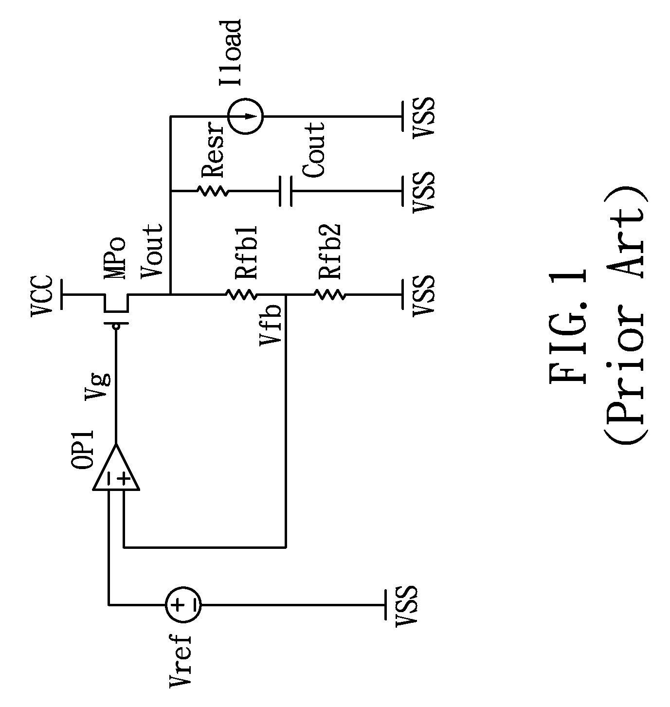
However, in the case when a very large current load is rapidly removed from a regulator (for example: five hundreds of milliamps to zero amp), the output voltage can rise to dangerously high levels and remain high for a long period of time before returning to regulation.
This high output voltage condition results when the output load current changes more rapidly than the amplifier can respond.
However, the reference voltage Vg can not reflect the variation of the Vout rapidly enough.
As a result, the voltage regulator disclosed in U.S. Pat. No. 5,864,227 is still not effective enough.
In addition, as the pull-down transistor used in the aforesaid voltage regulator is a P-MOSFET device that it is short of discharge efficiency since it is driven by a comparatively smaller current, the duration of returning the regulator back to regulation is still requiring to be improved.

Method used


Image

  • Voltage regulator with output accelerated recovery circuit
  • Voltage regulator with output accelerated recovery circuit
  • Voltage regulator with output accelerated recovery circuit

Examples


Embodiment Construction

[0009]For your esteemed members of reviewing committee to further understand and recognize the fulfilled functions and structural characteristics of the invention, several preferable embodiments cooperating with detailed description are presented as the follows.

[0010]Please refer to FIG. 2, which is a schematic circuit diagram of a low dropout voltage regulator according to an exemplary embodiment of the invention. The voltage regulator of FIG. 2 comprises: an operational amplifier OP1, a comparator Cl, an output transistor MPO, a pull-down transistor MNO, an output capacitor Cout, a first feedback resistor Rfb1, a second feedback resistor Rfb2, and a resistor Resr, being the equivalent series resistor of the output capacitor Cout. A source voltage VCC, a reference voltage Vref, and a biased voltage Vtrip are supplied to the voltage regulator. An output load current Iload, a gate voltage Vg, an output voltage Vout, and a feedback voltage Vfb are therefore generated in the voltage re...


PUM


Abstract

A voltage regulator with output accelerated recovery circuit is disclosed, which is substantially a low dropout voltage regulator (LDO) having a comparator and a pull-down transistor, both being connected between the positive feedback input node of its operational amplifier (OP) and the ground end thereof. In a preferred aspect, the comparator is used for detecting the voltage variation of a reference node, whereas the reference node is defined to be a node located between a first feedback resistor and a second feedback resistor. Operationally, as the voltage detected at the reference node is larger than a predetermined voltage, the pull-down transistor is forced to turn on so as to sink the output voltage rapidly for returning the same back into regulation.

Description

FIELD OF THE INVENTION[0001]The present invention relates to a voltage regulator with output accelerated recovery circuit, and more particularly, to an improved voltage regulator achieved by configuring additionally a comparator and a pull-down transistor into a conventional low dropout voltage regulator (LDO), both being connected between the positive feedback input node of its operational amplifier (OP) and the ground end thereof. In a preferred aspect, the comparator is used for detecting the voltage variation of a reference node, whereas the reference node is defined to be a node located between a first feedback resistor and a second feedback resistor so that the voltage of the positive feedback input node can be detected thereby. Operationally, as the voltage detected at the reference node is larger than a predetermined voltage, the pull-down transistor, being preferably an N-MOSFET, is forced to turn on so as to sink the output voltage (Vout) rapidly for returning the same bac...

Claims


Application Information

Patent Timeline
IPC IPC(8): G05F1/00
CPCG05F1/56
Inventor LIN, CHUNG-WEI
Owner HOLTEK SEMICON
Learn More