Method for Detection of Faulty Antenna Array Elements

a technology of antenna array elements and antenna arrays, applied in the direction of antennas, instruments, antenna radiation diagrams, etc., can solve problems such as antenna pattern distortion, and achieve the effects of eliminating reflection coefficient signals, reducing reflections from artifacts, and effectively isolating

Inactive Publication Date: 2008-04-24
RETRO REFLECTIVE OPTICS
View PDF4 Cites 4 Cited by
  • Summary
  • Abstract
  • Description
  • Claims
  • Application Information

AI Technical Summary

Benefits of technology

[0022] At the test station, the antenna array under test is placed in an anechoic chamber to minimize reflections from artifacts within the chamber or from the chamber walls themselves. Since the test signals projected by the transmit / receive antennas have a pulse repetition rate, time gating is utilized to eliminate returns from the irradiated antenna array that are the result of multi-path, thereby to eliminate corruption of the reflection coefficient signals from the frequency domain reflectometer.
[0023] While in one embodiment only a single transmit / receive antennas is effective, in a preferred embodiment as many as three transmit / receive antennas are utilized that irradiate the antenna array from slightly different angles. The use of slightly different angles permits even more information to be collected as to the returned signals so as to more effectively isolate which of the passive elements in the array are unterminated.
[0024] In order to take advantage of the multiple transmit / receive antenna configurations, rather than cross-correlating a template that is a 1-D vector, a template having a 2-D vector configuration is generated using the outputs of the three transmit / receive antennas.

Problems solved by technology

Not only can the existence of a defective antenna array be ascertained immediately, but also what elements in the array are unterminated and therefore causing a distorted antenna pattern.

Method used


Image

  • Method for Detection of Faulty Antenna Array Elements
  • Method for Detection of Faulty Antenna Array Elements
  • Method for Detection of Faulty Antenna Array Elements

Examples


Embodiment Construction

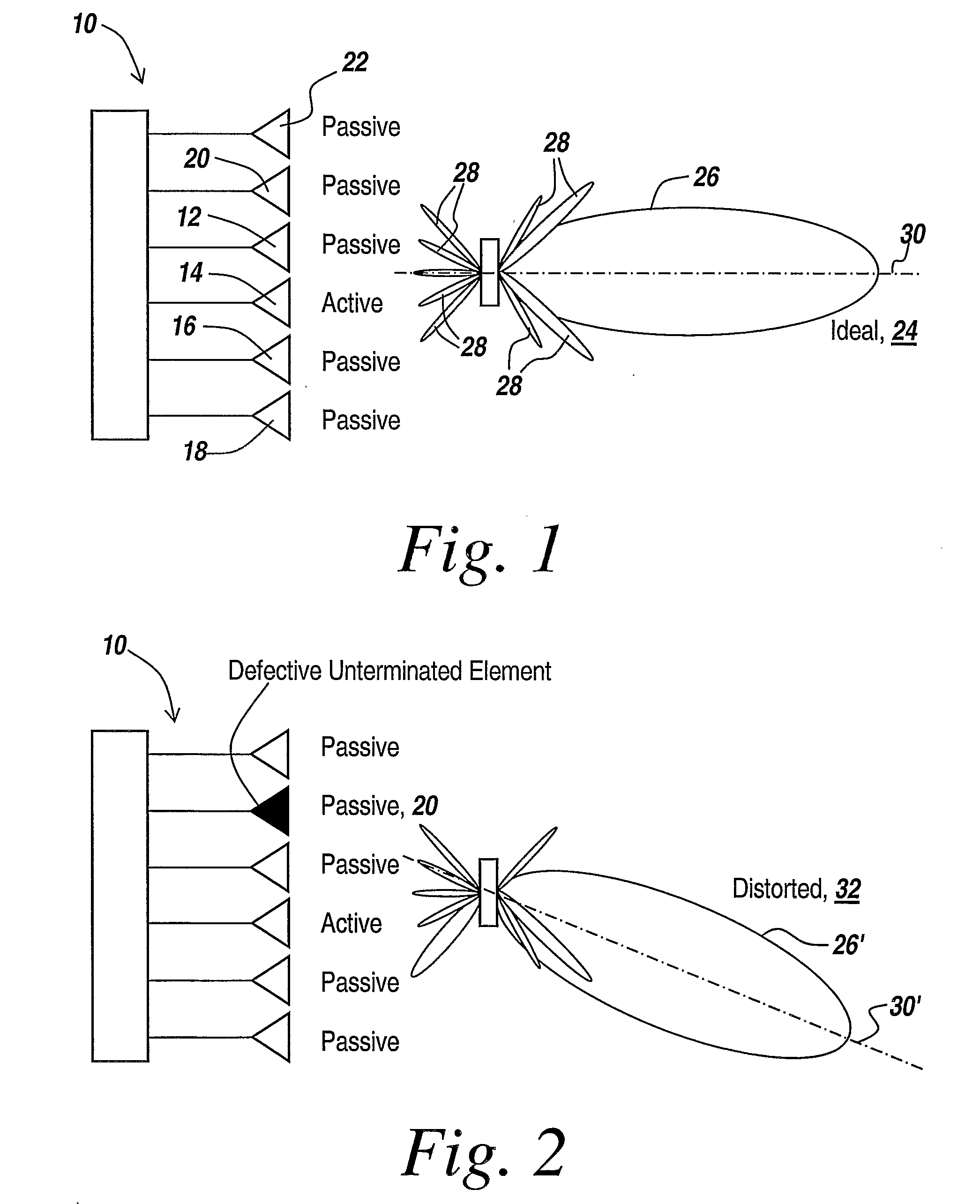
[0044] Referring now to FIG. 1, in order to test a multi-element antenna array 10 having an active element 12 and passive elements 14, 16, 18, 20 and 22, the ideal antenna array, hereinafter called the gold standard, produces an ideal antenna pattern 24 having a major lobe 26 and various side lobes 28, all symmetrical about the center line 30 of the array.

[0045] This ideal antenna pattern permits direction-finding applications in which the direction of incoming signals is determined through the directionality of the antenna array.

[0046] However, as illustrated in FIG. 2, assuming that antenna array 10 has a defective passive element 20 due to the fact, for instance, that the element is unterminated and therefore does not absorb incoming radiation, the entire array will have a distorted antenna pattern, here illustrated at 32, in which at the very least the axis of the major lobe 26′, namely axis 30′, is considerably altered with respect to the ideal axis as illustrated in FIG. 1. ...


PUM


Abstract

A method for early detection of faulty antenna arrays comprising the step of treating said detection as a special case of target recognition; wherein targets of interest are all previous examples of defective antenna arrays.

Description

RELATED APPLICATIONS [0001] This application claims rights under 35 USC § 119(e) from U.S. Application Ser. No. 60 / 665,784 filed Feb. 24, 2005, entitled Method For Detection of Faulty Antenna Array Elements, the contents of which are incorporated herein by reference.STATEMENT OF GOVERNMENT INTEREST [0002] The present invention was made with United States Government support under Contract No. N00019-02-C-3002 awarded by the US Air Force and Navy. The United States Government has certain rights in this invention.FIELD OF THE INVENTION [0003] This invention relates to detection of faulty antenna array elements and more particularly to a method for determining faulty unterminated elements in the antenna array. BACKGROUND OF THE INVENTION [0004] Antenna arrays having multiple elements have been used extensively in direction-finding in which the direction of the major lobe of the array, as well as the side lobe configuration, is determined by a number of active and passive elements in the...

Claims


Application Information

Patent Timeline
Patent Type & Authority Applications(United States)
IPC IPC(8): G01S7/40
CPCH01Q3/267
Inventor APOSTOLOS, JOHN T.BALL, RICHARD C.
Owner RETRO REFLECTIVE OPTICS
Why Eureka
Try Eureka