Plane light-source device

a light source device and plane technology, applied in the direction of diffusing elements, lighting and heating apparatus, instruments, etc., to achieve the effect of preventing lamp breakage and suppressing heat and electromagnetic waves

Inactive Publication Date: 2008-04-24
MITSUBISHI ELECTRIC CORP
View PDF4 Cites 17 Cited by
  • Summary
  • Abstract
  • Description
  • Claims
  • Application Information

AI Technical Summary

Benefits of technology

[0017]The present invention has been made to solve the problems described above, and an object of the present invention is, in a plane light-source device such as a direct-type backlight having lamps arranged behind a diffuser, to suppress influences of heat and electromagnetic waves generated by the lamps and to prevent breakage of the lamps on drop impact.
[0019]The covers reflect part of direct light propagating from the lamps toward the diffuser, so that a lamp image is less likely to appear at the light-emission surface of the diffuser. Also, the covers dissipate heat generated by the lamps and suppress heat conduction to the diffuser, thus preventing the diffuser from being warped, yellowed, or deformed by heat. Accordingly, the light-emission quality is less likely to deteriorate even when the distance between the diffuser and the lamps is reduced, which allows reduction of the thickness of the plane light-source device. Also, the covers are made of metal material or resin material with metal particles mixed therein, so that they can block electromagnetic waves generated by the lamps. Furthermore, the covers absorb heat generated by the lamps and dissipate it to the rear frame made of metal. As a result, in the liquid-crystal display apparatus using the plane light-source device, it is possible to suppress deterioration of display quality due to influences of electromagnetic waves and heat generated by the lamps.

Problems solved by technology

Furthermore, the covers absorb heat generated by the lamps and dissipate it to the rear frame made of metal.

Method used


Image

  • Plane light-source device
  • Plane light-source device
  • Plane light-source device

Examples


first preferred embodiment

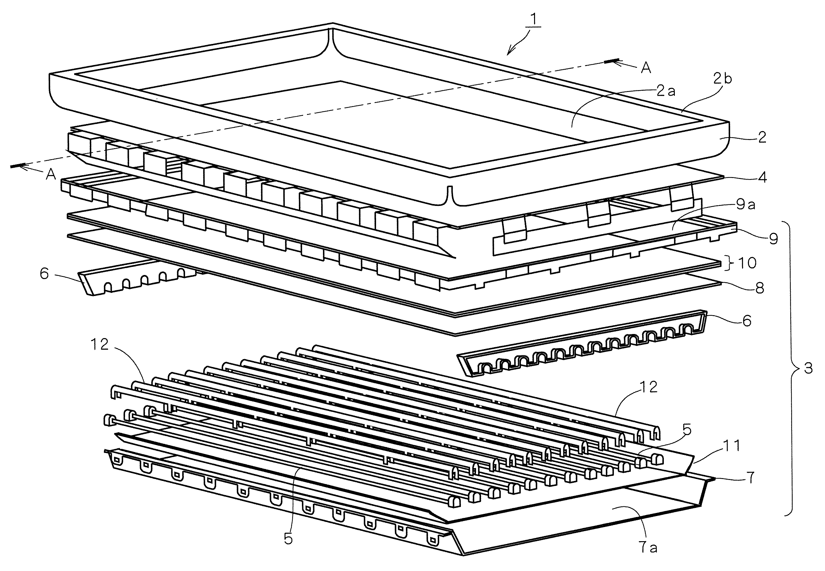
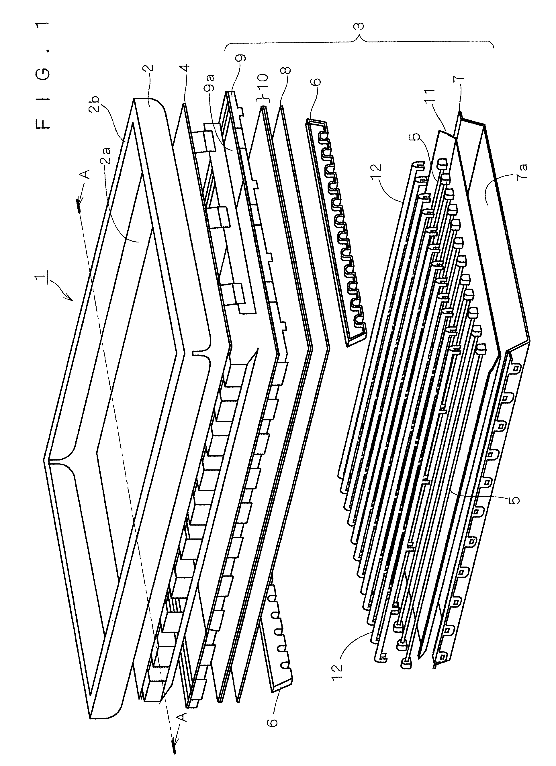
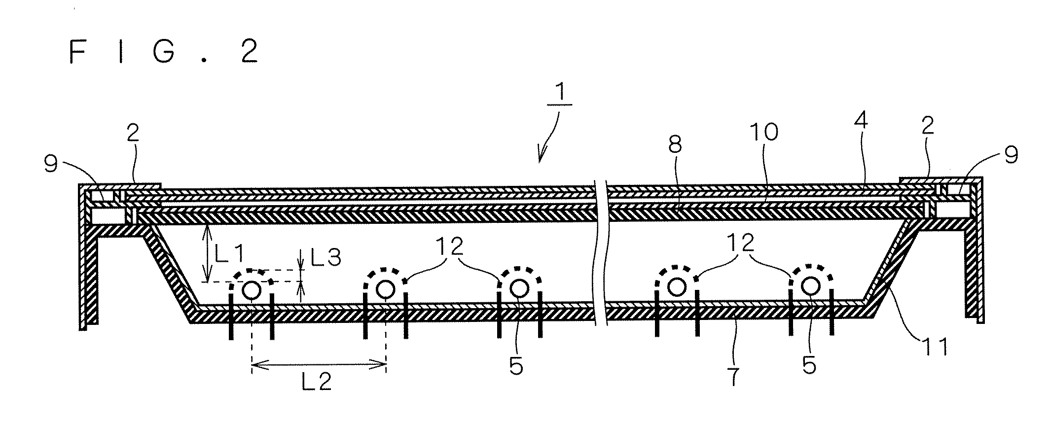
[0029]FIG. 1 is an exploded perspective view roughly illustrating the structure of a liquid-crystal display apparatus according to a first preferred embodiment, and FIG. 2 is a cross-sectional view of the liquid-crystal display apparatus. FIG. 2 corresponds to the cross section taken along line A-A in FIG. 1, and the same reference characters in FIGS. 1 and 2 denote the corresponding components.

[0030]As shown in FIG. 1, the liquid-crystal display apparatus 1 of this preferred embodiment chiefly includes a front frame 2 made of metal, a direct-type backlight unit 3 as a plane light-source device, and a rectangular plate-like liquid-crystal panel 4 held between them. For the sake of convenience of explanation, the display surface side of the liquid-crystal display apparatus 1 is herein defined as the upper side.

[0031]The front frame 2 has a rectangular opening 2a corresponding to the display area of the liquid-crystal panel 4, and a frame-like horizontal member 2b surrounding the open...

second preferred embodiment

[0062]This preferred embodiment illustrates a modification of the metal covers 12 for covering the lamps 5.

[0063]FIG. 5 is a perspective view of a metal cover 12 according to a second preferred embodiment, and FIG. 6 is a three-view drawing thereof. As can be seen from the diagrams, the metal cover 12 of the second preferred embodiment is smoothly corrugated approximately like a sine wave in the direction perpendicular to the lamps 5. Shaped in this way, the metal cover 12 has tapered projections 12d on its lower surface (on the lamp-side surface 12c). The structure is the same as that of the first preferred embodiment except for the corrugated shape of the metal cover 12. That is, the metal cover 12 of the second preferred embodiment also has legs 12a for engagement with the rear frame 7 and a large number of through holes 12b, and its lamp-side surface 12c has high reflectance. That is, this metal cover 12, too, has the light reflecting function, the heat dissipating function, and...

third preferred embodiment

[0066]FIG. 8 is a cross-sectional view of a liquid-crystal display apparatus according to a third preferred embodiment. As shown in this diagram, in this preferred embodiment, the metal covers 12 of the first preferred embodiment are replaced by metal covers 14 that are each formed like a flat-plate cantilever (hereinafter referred to as “cantilever-like covers 14”). As shown in FIG. 8, the cantilever-like covers 14 are fixed at an inclination to cover the lamps 5.

[0067]The cantilever-like covers 14, too, each have a large number of through holes and legs for engagement with the rear frame 7, and they have high reflectance at their lamp-side surfaces. That is, like the metal covers 12 of the first preferred embodiment, the cantilever-like covers 14 also have the light reflecting function, the heat dissipating function, and the electromagnetic wave blocking function, and thus provide the same effects as those of the first preferred embodiment. The cantilever-like covers 14 shaped lik...


PUM


Abstract

A plane light-source device having lamps disposed behind a diffuser is provided in which influences of heat and electromagnetic waves generated by the lamps are suppressed and the lamps are prevented from being broken on drop impact. A plane light-source device (a direct-type backlight) of a liquid-crystal display apparatus includes a plurality of lamps disposed side by side with a given pitch, a diffuser for diffusing light from the lamps, and metal covers disposed between the diffuser and the lamps. The metal covers each have a plurality of through holes, and they reflect light from the lamps at their respective surfaces that face the lamps.

Description

BACKGROUND OF THE INVENTION[0001]1. Field of the Invention[0002]The present invention relates to a plane light-source device that is used, e.g. as a backlight of a liquid-crystal display apparatus, and particularly to a technique to provide a plane light-source device with reduced thickness and uniform luminance.[0003]2. Description of the Background Art[0004]A non-light-emitting transmissive image display panel, such as a liquid-crystal display panel (a liquid-crystal panel), uses a plane light-source device called a backlight, which is provided in the rear of the display panel to radiate uniform light to the display surface. In general, such a backlight uses small-diameter cylindrical fluorescent tubes as light sources (hereinafter referred to as “lamps”), such as cold-cathode tubes or hot-cathode tubes. Known backlight structures include an edge-light type in which a lamp is disposed at an edge of a light guide plate, and a direct type in which a reflecting plate (hereinafter ref...

Claims


Application Information

Patent Timeline
Patent Type & Authority Applications(United States)
IPC IPC(8): G02B5/02F21V29/505
CPCF21V11/14G02F1/133606G02F1/133604G02F1/1333G02F1/1335
Inventor MATSUMOTO, SHIGEYUKI
Owner MITSUBISHI ELECTRIC CORP
Why Eureka
Try Eureka