
Method and System for Digital Tracking in Direct and Polar Modulation

a direct and polar modulation and digital tracking technology, applied in the field of wireless communication, can solve the problems of affecting the overall system solution of the mobile handset, the inability of the mobile multimedia processor to fully utilize the system-on-a-chip (soc) integration for today's the inability to fully utilize the system-on-a-chip (soc) integration for mobile handset advanced total system solution, etc., and the input signal that is being

Inactive Publication Date: 2008-04-24
AVAGO TECH WIRELESS IP SINGAPORE PTE
View PDF6 Cites 26 Cited by
  • Summary
  • Abstract
  • Description
  • Claims
  • Application Information

AI Technical Summary

Benefits of technology

[0011]These and other advantages, aspects and novel features of the present invention, as well as details of an illustrated embodiment thereof, will be more fully understood from the following description and drawings.

Problems solved by technology

Currently, mobile multimedia processors may not fully utilize system-on-a-chip (SoC) integration for advanced total system solution for today's mobile handsets.
For example, conventional mobile processors may utilize a plurality of hardware accelerators to enable a variety of multimedia applications, which significantly increases power consumption, implementation complexity, mobile processor real estate, and ultimately terminal size.
This may pose a particular problem when a cutoff frequency of the low pass filter is within the range of frequencies utilized by a direct modulation and / or polar modulation transmitter for transmitting signals.
As a result, an input signal that is being modulated by the direct modulation or polar modulation transmitter may become distorted.
In turn, the modulation output signal may become distorted.
The result is that the transmitted signal, when received at a receiver device, may not present a faith reproduction of the original input signal that was submitted for transmission.
However, one limitation of the use of analog control circuitry to control analog PLL circuitry may be component mismatches between components in the analog PLL circuitry that have a direct impact on the system performance.
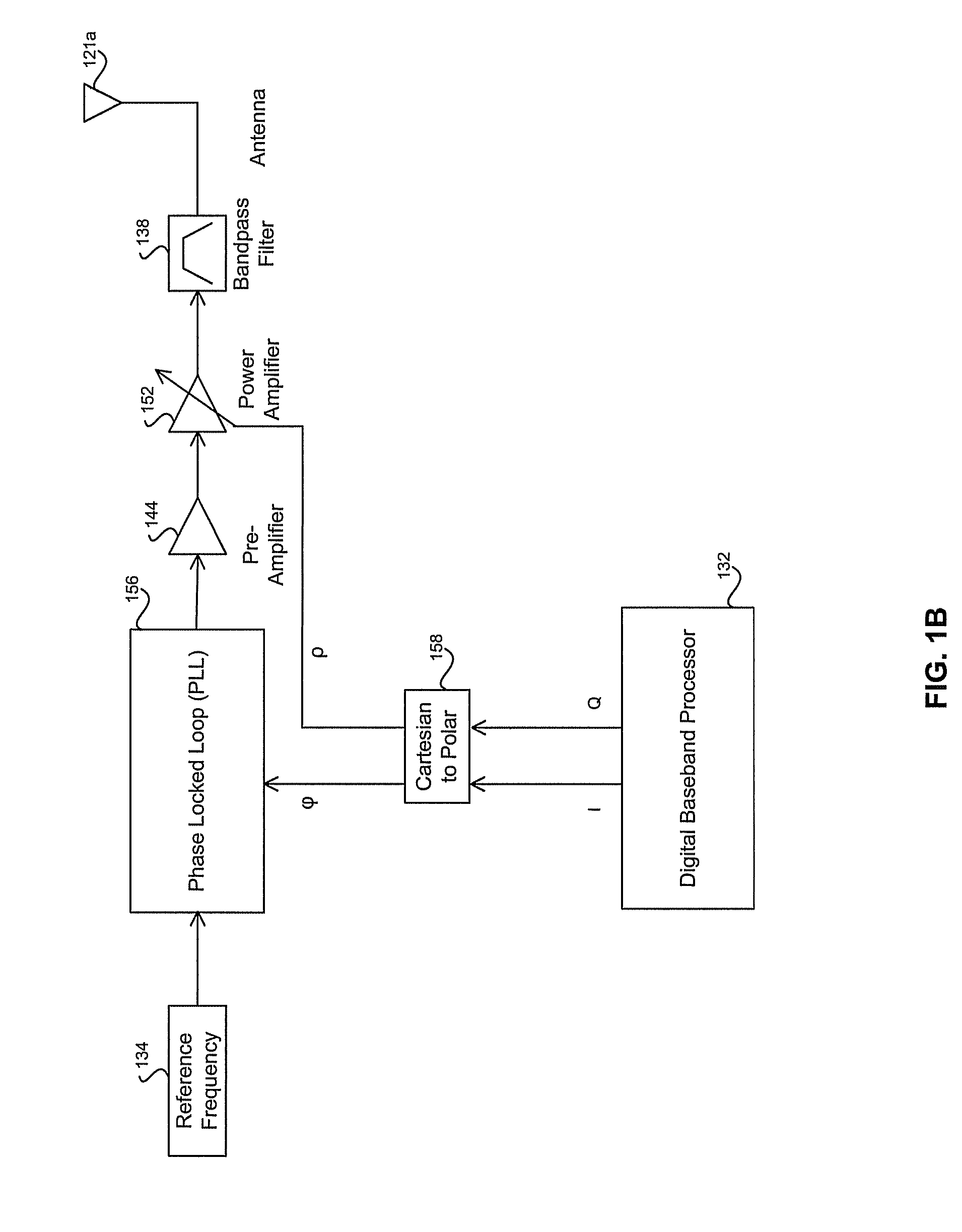
A limitation associated with the use of such circuitry in polar modulation transmitters may be the introduction of timing misalignment between the phase signal path, and the amplitude signal path for the input signals to the polar modulation transmitter.

Method used


Image

  • Method and System for Digital Tracking in Direct and Polar Modulation
  • Method and System for Digital Tracking in Direct and Polar Modulation
  • Method and System for Digital Tracking in Direct and Polar Modulation

Examples


Embodiment Construction

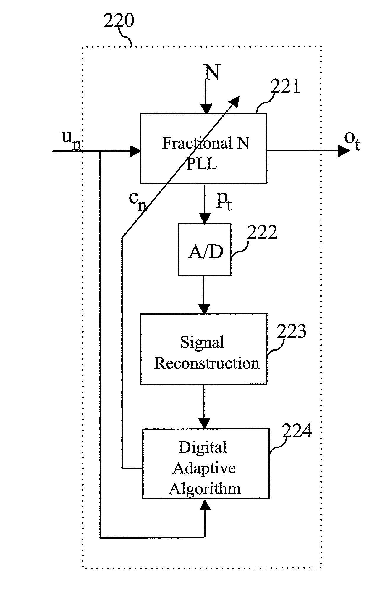
[0026]Certain embodiments of the invention relate to a method and system for digital tracking in direct and polar modulation. In various embodiments of the invention, analog component values in an analog PLL circuit may be controlled based on a digital control input signal that may be generated by digital control circuitry based on an analog feedback signal generated within the analog PLL circuit. The analog feedback signal may be continuously detected, or monitored, by the digital control circuitry with subsequent digital control signals generated based on current analog feedback signals. The continuous monitoring and generation of digital control signals in response to current analog feedback signals may be referred to as digital tracking. In this regard, various embodiments of the invention comprise a method and system for digital tracking of analog PLL circuitry. For analog PLL circuitry, which is utilized in a direct modulation transmitter, or polar modulation transmitter, vari...


PUM


Abstract

Aspects of a method and system for digital tracking in direct and polar modulation are presented. Aspects of the system may include at least one circuit within a phase locked loop (PLL) circuit that enables adaptive and digital control of an analog fractional N (Frac N) PLL during direct modulation of a signal or polar modulation of the signal.

Description

CROSS-REFERENCE TO RELATED APPLICATIONS / INCORPORATION BY REFERENCE[0001]Not Applicable.FIELD OF THE INVENTION[0002]Certain embodiments of the invention relate to wireless communication. More specifically, certain embodiments of the invention relate to a method and system for digital tracking in direct and polar modulation.BACKGROUND OF THE INVENTION[0003]Mobile communications have changed the way people communicate and mobile phones have been transformed from a luxury item to an essential part of every day life. The use of mobile phones today is dictated by social situations, rather than hampered by location or technology. While voice connections fulfill the basic need to communicate, and wireless voice and data connections continue to filter even further into the fabric of every day life, various integrated mobile multimedia applications, utilizing wireless and / or wired networks, may be the next step in the mobile communication revolution.[0004]Third generation (3G) cellular networ...

Claims


Application Information

Patent Timeline
IPC IPC(8): H04L27/12
CPCH03C5/00H04L27/148H04L27/18
Inventor FRANTZESKAKIS, EMMANOUILSFIKAS, GEORGIOS
Owner AVAGO TECH WIRELESS IP SINGAPORE PTE
Learn More