Balancing system for turbomachine rotor

a balancing system and rotor technology, applied in the direction of liquid fuel engines, vessel construction, marine propulsion, etc., can solve the problems of short the radial end portion is not easy to design, and the tangential stress is great, so as to minimize increase the service life of the balancing flange. , the effect of reducing the concentration of tangential stresses

Active Publication Date: 2008-04-24
SN DETUDE & DE CONSTR DE MOTEURS DAVIATION S N E C M A
View PDF3 Cites 22 Cited by
  • Summary
  • Abstract
  • Description
  • Claims
  • Application Information

AI Technical Summary

Benefits of technology

[0013]Consequently, the invention proposes an original manner of achieving the hold of the balance weights on the balancing flange, in both directions of the tangential line. Specifically, the pressure of the first screw against the first tangential end side of the first through-passageway makes it possible to immobilize the balance weight in the second direction of the tangential line relative to the flange, while the pressure of the second screw against the second tangential end side of the second through-passageway makes it possible to immobilize the balance weight in the first direction of the tangential line relative to this same flange. Consequently, the tangential attachment of each weight is advantageously provided without it being necessary to provide through-passageways of tangential width substantially equal to the diameter of the associated screw.
[0014]Consequently, this makes it possible to have greater freedom in the design of the radial end portion of the through-passageways, thereby offering the possibility of choosing the most suitable shape possible in order to minimize the concentration of tangential stresses being applied to said radial end portion.
[0015]Therefore, with the present invention in which each screw therefore has a diameter less than the tangential width of the passageway that it passes through, it becomes advantageously possible to adopt a passageway shape ensuring an increased service life of the balancing flanges, and also a reduction in the risks of deterioration of the latter.

Problems solved by technology

However, the achievement of the tangential hold of the balance weight explained above, namely by double pressure of each screw against respectively the two tangential end sides of the passageway, does not make it possible to offer great freedom in the design of the radial end portion of the passageway, which therefore remains under great tangential stress.
Therefore, the radial end portion and more particularly its radial summit forming a zone of great concentration of stresses, the service life of the balancing flange remains too short, and the risks of deterioration of this flange are very high.

Method used


Image

  • Balancing system for turbomachine rotor
  • Balancing system for turbomachine rotor
  • Balancing system for turbomachine rotor

Examples


Embodiment Construction

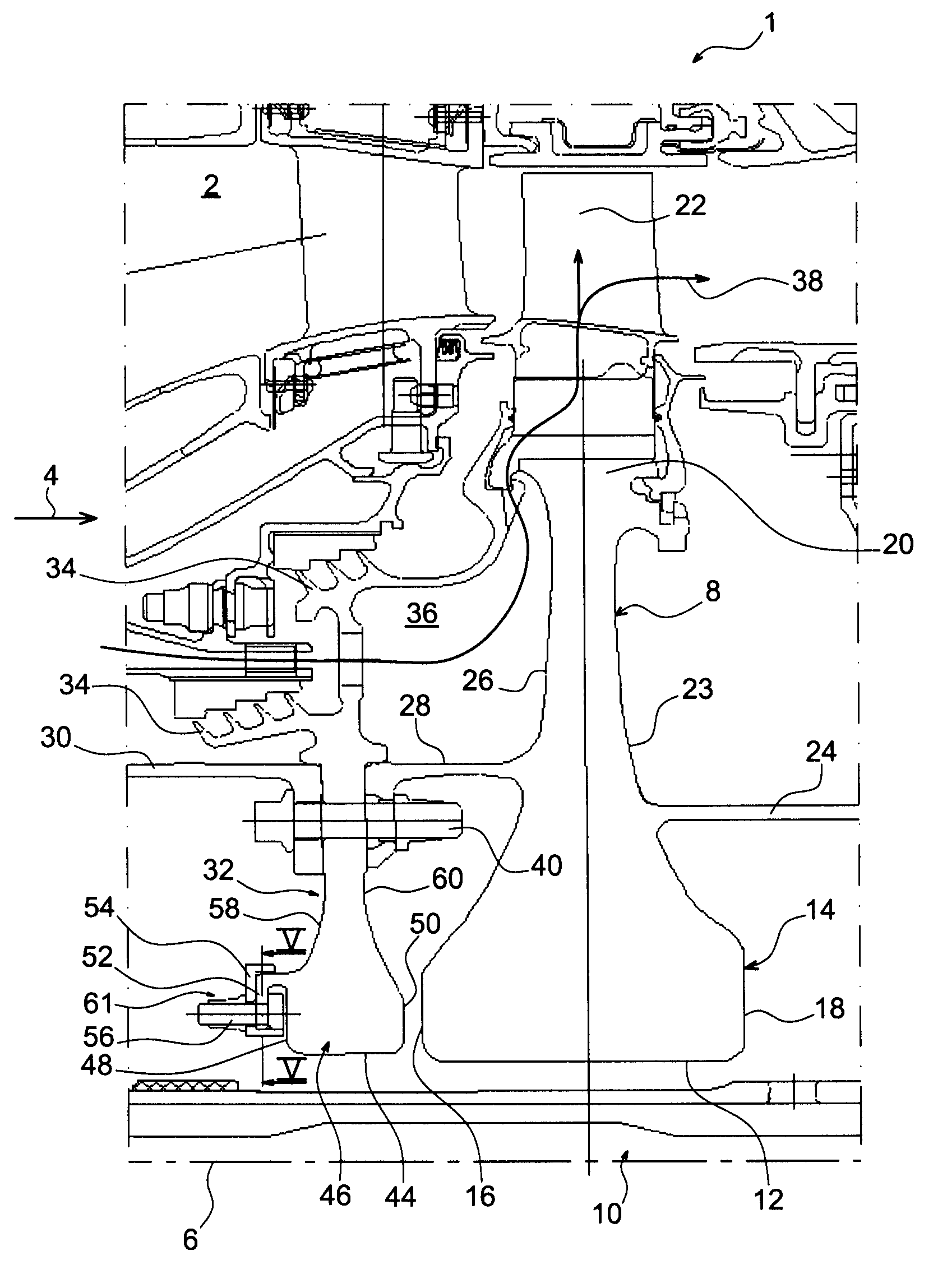
[0031]FIG. 1 shows a portion of a turbomachine module 1 according to a preferred embodiment of the present invention, this module here being a high pressure turbine called an HP turbine of the turbomachine, taking, for its part, the form of a turbojet for an aircraft.

[0032]In FIG. 1, the rotor portion of the HP turbine can be seen situated downstream of a combustion chamber 2 of the turbojet. In this respect, it is noted that the concepts “downstream” and “upstream” employed below are to be considered in relation to a main direction of flow of the gases through the turbomachine, indicated schematically by the arrow 4, this direction being substantially parallel to a longitudinal axis 6 of the turbojet corresponding simultaneously to an axis of the module 1 and of the disks comprising it.

[0033]Specifically, the module 1 comprises a main rotor disk called the blade support disk 8, with an axis 6 passing through a system of axes 10 of the turbojet thanks to the presence of a bore 12. M...


PUM


Abstract

The present invention relates to a turbomachine rotor balancing system comprising a balancing flange (52) provided with through-passageways (78), the system further comprising balance weights (54) each mounted fixedly on the flange (52) by means of a first and a second screw/nut assembly (56a, 56b) having a first and a second screw (84, 84) passing through a first and a second passageway (78, 78). According to the invention, said first screw is pressing against a first tangential end side (116) of the first through-passageway, and at a distance from a second tangential end side, and the second screw is pressing against a second tangential end side (118) of the second through-passageway, and at a distance from the first tangential end side.

Description

BACKGROUND OF THE INVENTION[0001]The present invention relates in a general manner to a turbomachine rotor balancing system and to a turbomachine module comprising at least one such balancing system.[0002]The invention also relates to a turbomachine fitted with at least one such module, the turbomachine preferably taking the form of a turbojet for an aircraft.DESCRIPTION OF THE PRIOR ART[0003]On existing turbomachine modules, such as compressors or turbines, a rotor balancing system is usually provided comprising an annular balancing flange on which balance weights are mounted with the aid of bolts housed in through-passageways of the annular flange. The weights may therefore be distributed around the flange in the desired manner, providing a good balancing of the associated turbomachine module. Accordingly, this type of rotor balancing system is usually qualified as modular.[0004]More precisely, the annular balancing flange usually comprises an annular core delimited radially in a ...

Claims


Application Information

Patent Timeline
Patent Type & Authority Applications(United States)
IPC IPC(8): F01D5/10F01D5/02F16F15/32
CPCF01D5/027F05D2230/64Y02T50/671F04D29/662Y02T50/60
Inventor BLANCHARD, STEPHANE PIERRE GUILLAUMEGARIN, FABRICEJUDET, MAURICE GUYLANGEVIN, THOMAS
Owner SN DETUDE & DE CONSTR DE MOTEURS DAVIATION S N E C M A
Why Eureka
Try Eureka