
Cache memory having pipeline structure and method for controlling the same

Active Publication Date: 2008-04-24
RENESAS ELECTRONICS CORP
View PDF1 Cites 15 Cited by
  • Summary
  • Abstract
  • Description
  • Claims
  • Application Information

AI Technical Summary

Benefits of technology

[0021]In the cache memory according to the one embodiment of the present invention, it is possible to reflect an update result of the tag memory due to the occurrence of the miss hit in a preceding memory access request on the hit decision in a subsequent memory access request even when the miss hit occurs in the preceding memory access request. Therefore, it is possible to prevent an incorrect decision when the hit decision is made in response to the subsequent memory access request, to suppress an unwanted data refill behavior, and to avoid outputting the incorrect data from the data memory.
[0024]According to the present invention, even when a multi-staging of the pipeline of the cache memory is developed, it is possible to provide the cache memory that is able to efficiently process a successive memory accesses.

Problems solved by technology

The number of pipeline stage of the cache memory is typically two because the increase of the cache access time is undesirable.
However, in the cache memory having the two-stage pipeline as stated above, it is difficult to improve operating frequency of the cache memory 8 because it executes large amount of operations in one stage, and it is impossible to make the whole process fast enough to be satisfied (impossible to improve throughput of the cache memory 8).
However, as a number of pipeline stages of a cache-memory is increased, the present inventor has faced a problem as described below which prevents an efficient behavior of the cache memory.
The problem here is that this update result of the tag memory due to the occurrence of the miss hit is not reflected to the hit decision made in response to the memory access request which is made immediately after the miss hit occurs.
However, this architecture also causes other problems that a hardware size is increased and a complexity of a control section for controlling a retry sequence is increased.

Method used


Image

  • Cache memory having pipeline structure and method for controlling the same
  • Cache memory having pipeline structure and method for controlling the same
  • Cache memory having pipeline structure and method for controlling the same

Examples


Embodiment Construction

[0031]The invention will be now described herein with reference to illustrative embodiments. Those skilled in the art will recognize that many alternative embodiments can be accomplished using the teachings of the present invention and that the invention is not limited to the embodiments illustrated for explanatory purposes.

[0032]A specific embodiment to which the present invention applies will now be described in detail below with reference to the drawings. In each drawing, the same reference numerals are used for the same components. The overlapping description is appropriately omitted for the sake of clarity.

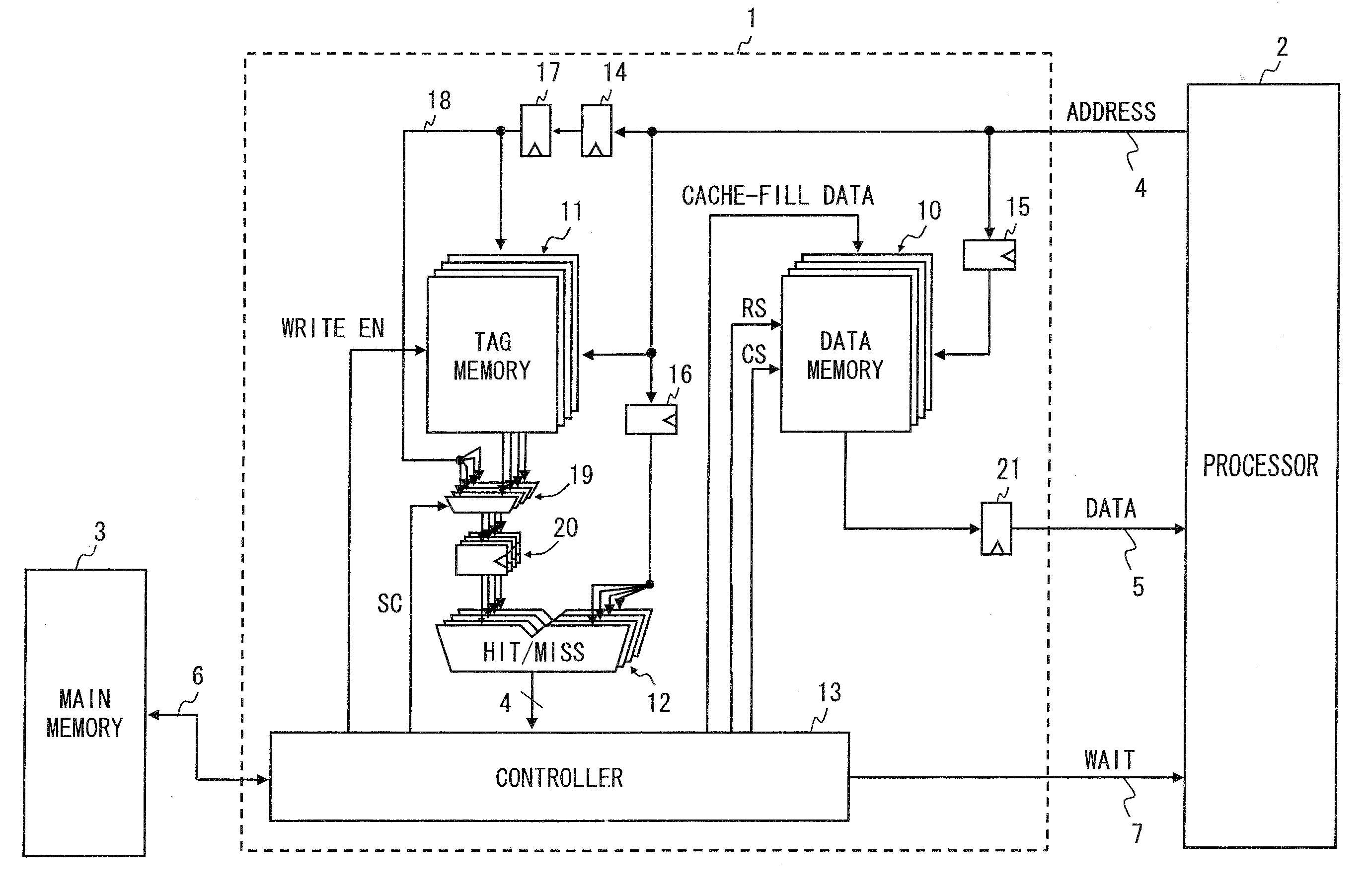
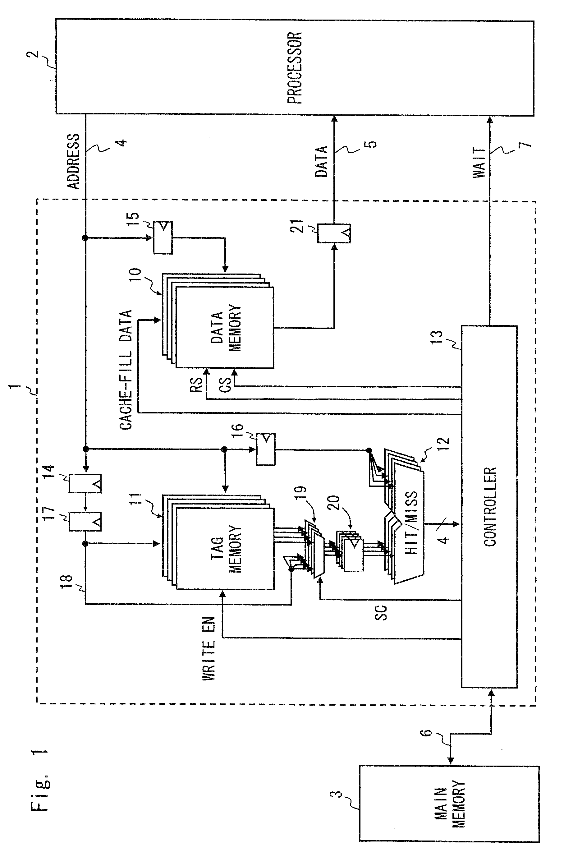
[0033]A configuration of a cache memory 1 according to the present embodiment is shown in FIG. 1. The cache memory 1 is a four-way set associative type cache memory. We assume that the cache memory here is the four-way set associative configuration so that the cache memory 1 and a cache memory 8 of a Related Art shown in FIG. 5 are easily compared. However, such a configurati...


PUM


Abstract

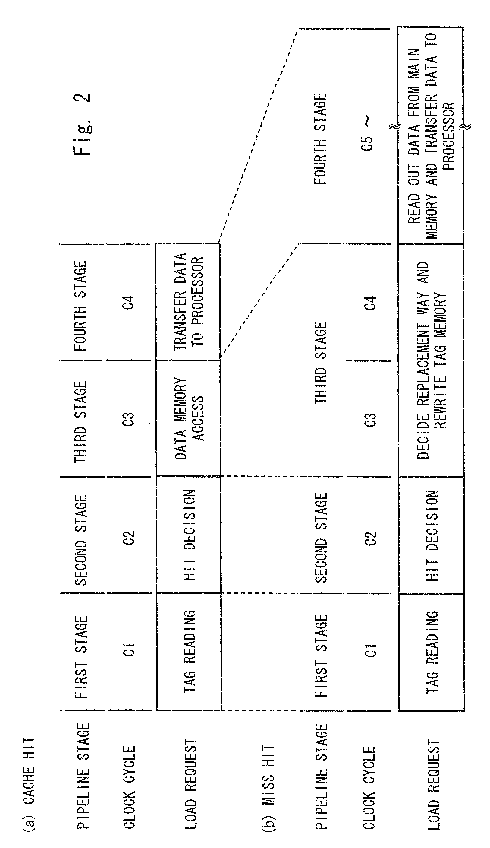
One embodiment of the present invention is a cache memory arranged between a processor and a low-speed memory and performing a pipeline processing of a memory access made by the processor. In a first stage, the cache memory reads out a tag address from a tag memory. In a second stage, the cache memory performs a hit decision by a hit decision unit. When the hit decision result is a miss hit, the cache memory performs an update control of the tag memory and a behavior control of a bypass circuit for supplying a data held in a latch circuit to the hit decision unit by bypassing the tag memory in a third stage. The latch circuit is configured to hold a tag address included in a input address supplied from the processor. When the hit decision result is the miss hit, the cache memory further performs an update of the data memory by reading out of the data from the low-speed memory and an outputting of the data read out from the low-speed memory to the processor in a fourth stage just after the third stage or in the later stage.

Description

BACKGROUND OF THE INVENTION[0001]1. Field of the Invention[0002]The present invention relates to a cache memory configured to perform a pipeline processing of a memory access from a processor.[0003]2. Description of Related Art[0004]A cache memory that uses a clock synchronous SRAM (synchronous SRAM) and adopts a pipeline structure has been put to practical use. A cache memory having a pipeline structure is arranged between a processor and a low-speed memory and processes a memory access request from the processor by the pipeline which is divided into a plurality of process stages (see Japanese Unexamined Patent Application Publication No. 10-63575, for example). The processor that performs a memory access to the cache memory having the pipeline structure is typically a RISC (Reduced Instruction Set Computer) type microprocessor. The processor may be the one of a CISC (Complex Instruction Set Computer) type or may be a DSP (Digital Signal Processor) for performing a digital signal p...

Claims


Application Information

Patent Timeline
IPC IPC(8): G06F12/00
CPCG06F12/0855G06F12/0864G06F12/0859G06F12/0846G06F12/0888G06F9/38G06F12/00
Inventor CHIBA, SATOSHIKATO, TAKUMI
Owner RENESAS ELECTRONICS CORP
Learn More