Foot anti-contamination barrier membrane structure

a technology of anti-contamination barrier and foot, which is applied in the field of foot anti-contamination barrier membrane structure, to achieve the effect of easy and quick removal

Inactive Publication Date: 2008-05-01
GARRETT ARLENE I L
View PDF12 Cites 15 Cited by
  • Summary
  • Abstract
  • Description
  • Claims
  • Application Information

AI Technical Summary

Benefits of technology

[0003]Preferably, these thin underfoot barriers are constructed so that they will adhere relatively tenaciously during the short periods of time that they are worn and walked upon, and that they have structural qualities which allow them, despite their preferable gossamer characteristic, to stay intact during short periods of use, and also to stay relatively well adhered to the bottoms of feet, stockings, etc. during use.
[0005]Also, the specific material forming this barrier structure should be such that it will confidently prevent true contamination with respect to any pathogenic contaminant which might be picked up from foot / stocking / sock contact with the floor surface where they are used.
[0010]FIG. 4 illustrates a point in time slightly later than that which is illustrated in FIG. 3, and specifically shows how, when the now barrier-guarded foot lowers into contact with the airport concourse floor (in this illustration shown as a carpeted floor), the gossamer and drapey nature of the barrier sheet causes it to form and reshape itself to provide intimate adhesion contact with the sole of the foot—a feature of the invention which promotes successful use of a low-tack, repositionable adhesive without creating a situation where an applied barrier shape is likely to break away from the foot sole during a short period of use.

Problems solved by technology

With regard to many people who are airline passengers, objections and concerns have arisen, and have been voiced, regarding the fact that, when shoes are removed in safety-screening areas, with the result that people must then committedly walk substantially or actually barefooted on the safety-screening area floor (carpeted or not), there is a potential for floor contact foot exposure to pathogenic contaminants which could cause illness.

Method used


Image

  • Foot anti-contamination barrier membrane structure
  • Foot anti-contamination barrier membrane structure

Examples


Embodiment Construction

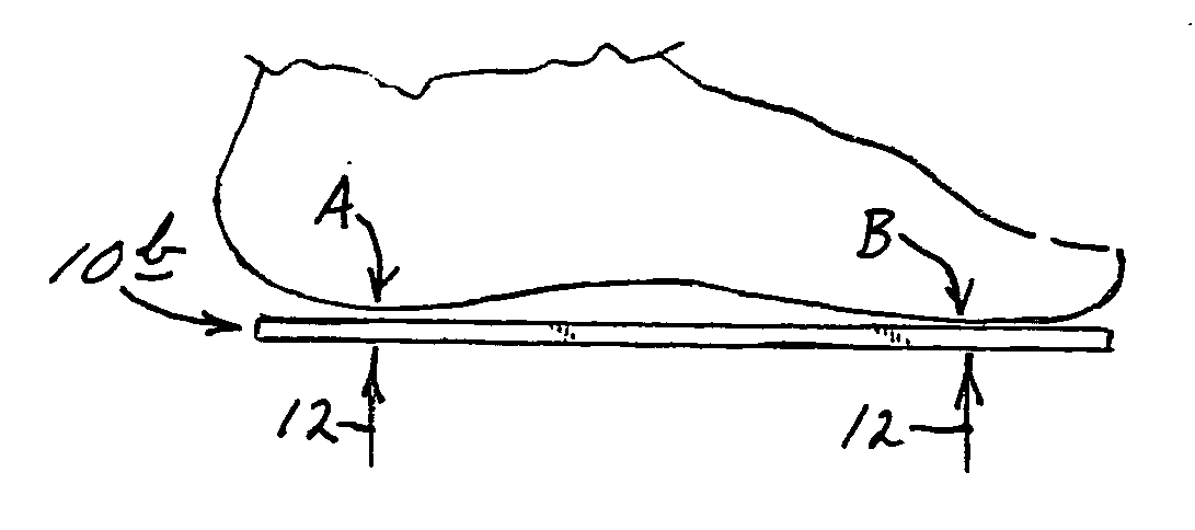
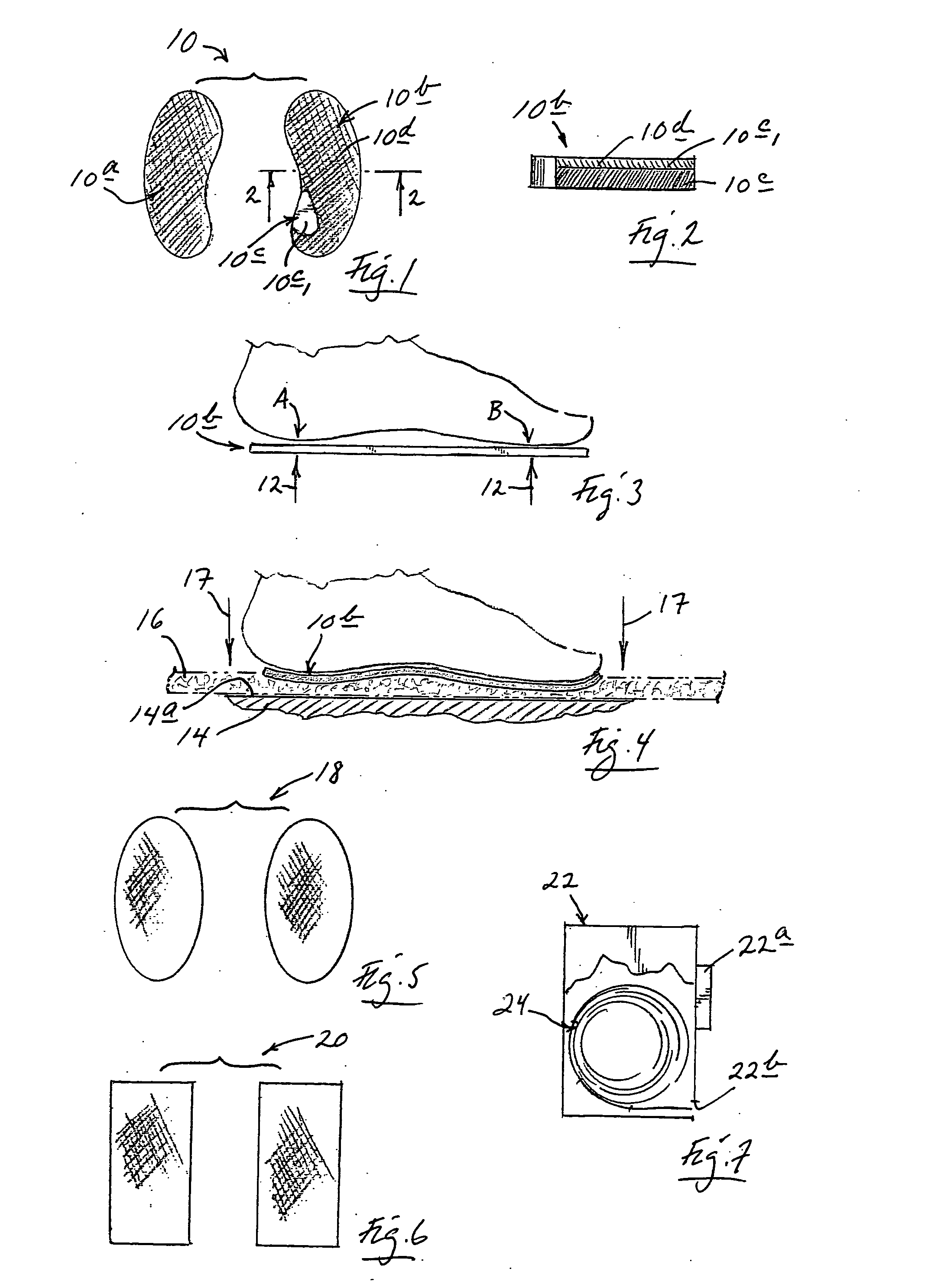
[0013]Turning attention now to the drawings, and referring first of all to FIGS. 1 and 2, illustrated generally at 10 in FIG. 1 is pair of foot barrier sheets 10a, 10b which, as illustrated in FIG. 1, have perimetral outlines that possess essentially left-foot and right-foot outlines, respectively. The “toe ends” of these sheets are shown pointing upwardly in FIG. 1. Barrier sheet 10b, which is to be applied to the underside (sole) of the right foot of a user, is shown in cross section in FIG. 2 on a scale which is significantly larger than that employed in FIG. 1. FIG. 2 specifically illustrates that each of these barrier sheets is formed with an underlayer, preferably, of a gossamer-thin, flexible and drapey sheet material, such as the commercially available material sold under the trademark Tyvek®10c, the upper surface, or face, 10c1 of which, i.e., the intended foot-attaching adhesion surface, or face, being suitably coated with what is known as a low-tack, repositionable adhesi...


PUM


Abstract

Disposable, anti-pathogen, anti-contamination barrier membrane structure characterized with drape, and adapted to be interposed the sole of the foot and a walking surface including (a) gossamer-thin, flexible, pathogen-blocking, sheet-like barrier material having an adhesion face, placeable, adhesively and removably, with light pressure, onto, and fully covering, from a perimetral point of view, the sole of a person's foot, and (b) low-tack, re-positionable adhesive structure resident on the adhesion face.

Description

BACKGROUND AND SUMMARY OF THE INVENTION[0001]At commercial airports distributed around the United States and elsewhere in the world, ticketed passengers are now routinely subjected to a regular security screening process before they are permitted to enter the relevant boarding-gate concourses. This screening process now almost routinely either requires, or strongly encourages, that, before a person passes through a personnel security-screening gate, that person's shoes be removed, with such shoes, and other passenger-carried items, being directed independently through a weapons and contraband scanning tunnel on a conveyor belt which collects these items typically at a point which is some distance, perhaps several yards, away from where they are ultimately returned to their owning passengers. With regard to many people who are airline passengers, objections and concerns have arisen, and have been voiced, regarding the fact that, when shoes are removed in safety-screening areas, with ...

Claims


Application Information

Patent Timeline
Patent Type & Authority Applications(United States)
IPC IPC(8): A43B3/12A43B19/00A63B71/12
CPCA43B1/0045A43B13/28A43B7/00
Inventor GARRETT, ARLENE I. L.
Owner GARRETT ARLENE I L
Why Eureka
Try Eureka