Drive control device of motor and a method of start-up

a technology of a control device and a motor, which is applied in the direction of motor/generator/converter stopper, electronic commutator control, dynamo-electric converter control, etc., can solve the problems of reducing the average torque during the initial acceleration, increasing the startup time to a predetermined rotation speed correspondingly, and preventing torque variation. , the effect of reducing the startup tim

Inactive Publication Date: 2008-05-01
RENESAS ELECTRONICS CORP
View PDF3 Cites 42 Cited by
  • Summary
  • Abstract
  • Description
  • Claims
  • Application Information

AI Technical Summary

Benefits of technology

[0011]According to this aspect, in the first operation, the direction of rotation is determined based on the detected position of the rotor, and in the second operation, continuous energization is

Problems solved by technology

In an application where startup and stop of the motor are alternated frequently, a use in a relatively quiet environment, and a motor use in a hand-held device used close to a user's ear, such noise at motor startup grates on the ear.
Further, si

Method used


Image

  • Drive control device of motor and a method of start-up
  • Drive control device of motor and a method of start-up
  • Drive control device of motor and a method of start-up

Examples


Embodiment Construction

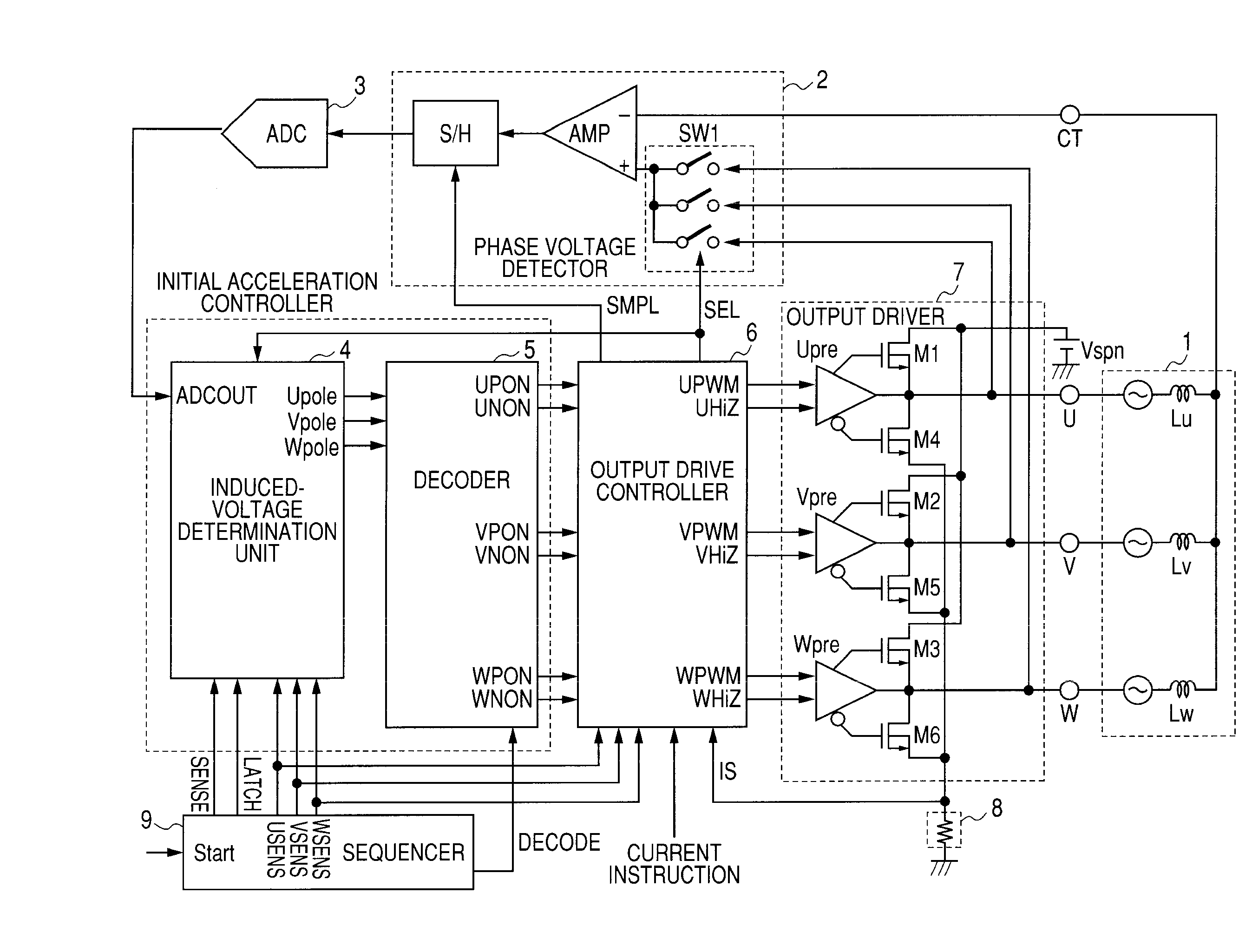
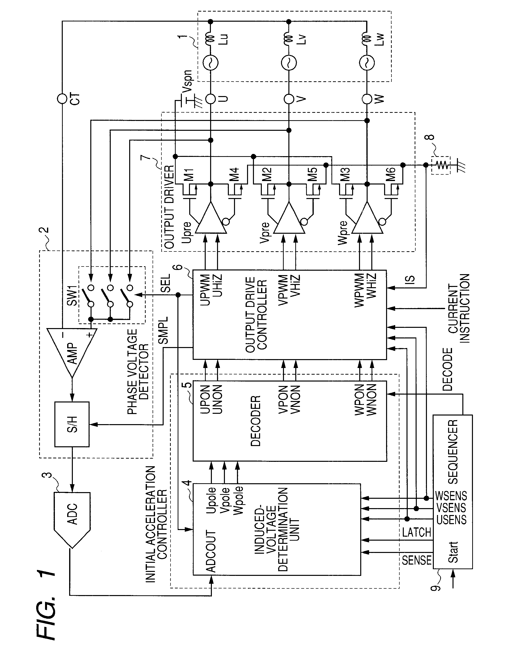
[0025]FIG. 1 is a block diagram showing a startup-related section of a motor drive control device according to an embodiment of the present invention. Motor coils Lu, Lv, and Lw of a three-phase motor 1 are PWM-driven by an output driver 7. The output driver 7 is composed of power MOSFETs M1 to M6 and spindle output predrivers Upre, Vpre, Wpre. An output drive controller 6 generates output control signals UPWM, UHIZ, VPWM, VHIZ, WPWM, and WHIZ, which are inputted to the spindle output predrivers Upre, Vpre, and Wpre.

[0026]A DC shunt resistor 8 is used to detect a motor drive current. That is, the DC shunt resistor 8 provided between the common junction point of the power MOSFETs M4, M5, and M6 in the lower part of an output stage and a circuit ground detects a voltage IS, a sense amplifier included in the output drive controller 6 amplifies the detected voltage IS, and an analog-to-digital converter converts the amplified signal into a digital signal. A current controller included i...


PUM


Abstract

A motor drive control device and motor startup method prevent startup noise and reduce startup time. At startup, a current to which a rotor does not react is passed through two phase coils of a polyphase DC motor in succession, and a voltage polarity induced in a non-conducting phase is detected. A first operation decodes the detected signal, and determines phase coils of the motor through which a current should pass to rotate the rotor and the energization direction. A second operation forms a control signal for passing a current according to the determination to drive the motor, detects a voltage peak induced in the non-conducting phase during the drive, and performs switching control of a conducting phase. In normal operation, the position of the rotor is detected based on a back EMF in each phase, and rotation control is performed.

Description

CROSS-REFERENCE TO RELATED APPLICATIONS[0001]The disclosure of Japanese Patent Application No. 2006-295056 filed on Oct. 31, 2006 including the specification, drawings and abstract is incorporated herein by reference in its entirety.BACKGROUND OF THE INVENTION[0002]The present invention relates to a technique effective when applied to a drive control technique for a brushless motor and startup control of a three-phase DC motor, and to a technique effective when applied to a drive control device of a spindle motor for rotationally driving a storage medium in a disk storage device such as a hard disk drive (HDD).[0003]A brushless three-phase DC motor generally called a spindle motor is used to rotate a magnetic disk as a storage medium in a hard disk drive. The magnetic disk is rotated at high speed by the spindle motor, and a magnetic read / write head is brought close to the surface of the rotating magnetic disk and moved in a radial direction to write or read information. The followi...

Claims


Application Information

Patent Timeline
IPC IPC(8): H02P1/18H02P6/06H02P6/08H02P6/18H02P6/182
CPCG11B19/2054H02P6/20H02P6/182
Inventor KUROSAWA, MINORUKOKAMI, YASUHIKO
Owner RENESAS ELECTRONICS CORP
Why Eureka
Try Eureka