Method and apparatus for shielding feedthrough pin insulators in an ionization gauge operating in harsh environments

a technology of ionization gauge and feedthrough pin, which is applied in the direction of discharge tube/lamp details, fluid pressure measurement, instruments, etc., can solve the problems of same gauge failing in hours or even minutes, and achieve the effect of increasing the overall operational life of the hot-cathode ionization gauge and increasing the overall operational life of the ionization gaug

Inactive Publication Date: 2008-05-01
MKS INSTR INC
View PDF15 Cites 19 Cited by
  • Summary
  • Abstract
  • Description
  • Claims
  • Application Information

AI Technical Summary

Benefits of technology

[0004]Embodiments of an ionization gauge are provided that increase the overall operational lifetime of a hot-cathode ionization gauge. An example embodiment includes at least one electrode, an electrical feedthrough pin that connects to the at least one electrode, an insulator that connects to and surrounds the electrical feedthrough pin, and a shield associated with the electrical feedthrough pin. The shield is configured to shield the insulator from material that may deposit on the insulator and cause electrical leakage between the electrical feedthrough pin and nearby gauge components. The material may include material from a vacuum process or material sputtered from surfaces of the ionization gauge. As a result, embodiments of the shield increase the overall operational lifetime of an ionization gauge.

Problems solved by technology

However, these same gauges fail in hours or even minutes when operated in harmful environments of certain vacuum processes that involve, for example, high pressures or certain gas types.

Method used


Image

  • Method and apparatus for shielding feedthrough pin insulators in an ionization gauge operating in harsh environments
  • Method and apparatus for shielding feedthrough pin insulators in an ionization gauge operating in harsh environments
  • Method and apparatus for shielding feedthrough pin insulators in an ionization gauge operating in harsh environments

Examples


Embodiment Construction

[0017]A description of preferred embodiments of the invention follows.

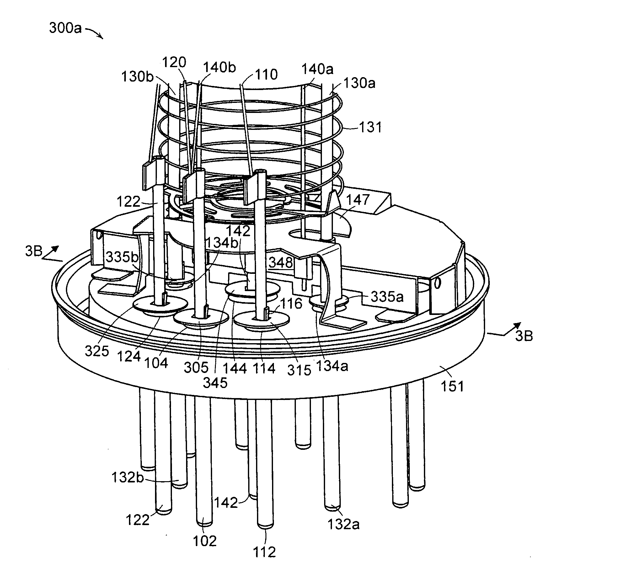
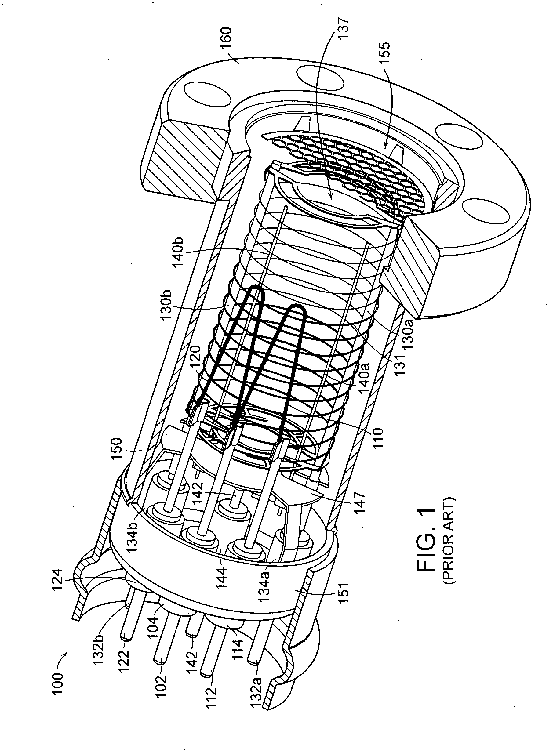
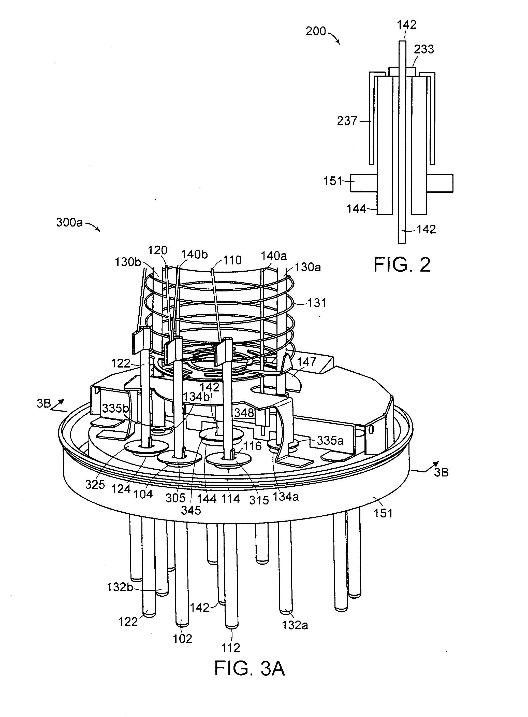
[0018]FIG. 1 is a perspective view of an example hot-cathode ionization gauge 100 according to the prior art, illustrating feedthrough pin insulators that benefit from embodiments of a feedthrough pin insulator shield. The hot-cathode ionization gauge 100 includes a cylindrical wire grid 131 (i.e., anode) defining an ionization volume 137 (i.e., anode volume). Two ion collector electrodes 140a, 140b are disposed within the ionization volume 137 and two cathodes 110, 120 are disposed external from the cylindrical wire grid 131. The ion collector electrodes 140a, 140b are joined at one of their ends by a supporting structure 348 illustrated in FIG. 3A. The supporting structure 348, in turn, is mounted to a feedthrough pin 142.

[0019]The hot-cathode ionization gauge 100 also includes a collector shield 147, such as a stainless steel shield, to shield various components of the ionization gauge from ionized process gas ...


PUM

PropertyMeasurementUnit
voltageaaaaaaaaaa
electron emission currentaaaaaaaaaa

Abstract

Shields for feedthrough pin insulators of a hot cathode ionization gauge are provided to increase the operational lifetime of the ionization gauge in harmful process environments. Various shield materials, designs, and configurations may be employed depending on the gauge design and other factors. In one embodiment, the shields may include apertures through which to insert feedthrough pins and spacers to provide an optimal distance between the shields and the feedthrough pin insulators before the shields are attached to the gauge. The shields may further include tabs used to attach the shields to components of the gauge, such as the gauge's feedthrough pins. Through use of example embodiments of the insulator shields, the life of the ionization gauge is extended by preventing gaseous products from a process in a vacuum chamber or material sputtered from the ionization gauge from depositing on the feedthrough pin insulators and causing electrical leakage from the gauge's electrodes.

Description

BACKGROUND OF THE INVENTION[0001]The most common hot-cathode ionization gauge is the Bayard-Alpert (B-A) gauge. The B-A gauge includes at least one heated cathode (or filament) that emits electrons toward an anode, such as a cylindrical wire grid, defining an anode volume (or ionization volume). At least one ion collector electrode may be disposed within the anode volume. The anode accelerates the electrons away from the cathode towards and through the anode. Eventually, the anode collects the electrons.[0002]In their travel, the electrons impact gas molecules and atoms and create positive ions. The positive ions are then urged to the ion collector electrode by an electric field created in the anode volume by the anode and the ion collector electrode. The electric field may be created by applying a positive voltage to the anode and maintaining the ion collector electrode at ground potential. A collector current is generated in the ion collector electrode as ionized atoms collect on ...

Claims


Application Information

Patent Timeline
Patent Type & Authority Applications(United States)
IPC IPC(8): G01L21/30
CPCY10T29/49002H01J41/04
Inventor KNOTT, RICHARD A.
Owner MKS INSTR INC
Why Eureka
Try Eureka