Display cursor control device with enhanced multiple dimensional tilt angle operation

a cursor control and multi-dimensional technology, applied in the field of display cursor control devices, can solve the problems of complex implementation, increased cost, and difficulty of each type of device, and achieve the effects of convenient control of the movement of the cursor, enhanced convenience of device tilting movements, and flexible operation

Inactive Publication Date: 2008-05-01
IMU SOLUTIONS
View PDF7 Cites 17 Cited by
  • Summary
  • Abstract
  • Description
  • Claims
  • Application Information

AI Technical Summary

Benefits of technology

[0011]One aspect of this invention is to provide a cursor control device that can flexibly operate without requiring the device to move along a flat surface. Specifically, a new control device configuration is provided with either a curve bottom surface to enhance the convenience of device tilting movements. Alternately, a device pad with curve surface is provided to provide a tilting angle of the control device when the control device is moved along the curved surface of the device pad. Operation of the mouse along a curved surface pad provides the advantage that the operation of such mouse is generally similar to the operation of a conventional mouse.
[0012]More specifically, a cursor control device or a point device pointing to a display image is disclosed that has a curved bottom, e.g., an elliptical shape bottom surface. A user of the device can easily control the movement of a cursor or a display image by conveniently tilting the device in all directions with minimum hand and wrist movements. Such device requires very small surface area on a desk or on any surface for supporting the lowest contact area of the curve bottom surface. It is understood that such surface support may be optional because the cursor can be moved by tilting the control device that can be performed under the condition that the control device is placed on a surface or lift up from a supporting surface without support.
[0013]Another aspect of the invention is to provide an improved cursor control device or an image point device with improved signal process of the measurements from an acceleration sensor, i.e., accelerometer, by providing different sensitivities for the acceleration measurements along different angular orientations. Such different sensitivities are implemented to compensate for the differences in freedom of angular movements along different angular orientations of the wrist in tilting the device when the device is support on a surface. Specifically, the acceleration measurements are processed with greater sensitivity in measuring tilt angle along a vertical direction in controlling the up and down of the cursor than the sensitivity of right or left tilt movements in controlling the cursor in moving to the right or left side respectively.
[0014]Another aspect of the invention is to provide an improved cursor control device or an image point device with improved signal process of the measurements from an acceleration sensor, i.e., accelerometer, by providing different sensitivities for the acceleration measurements at different movement speed. Specifically, when the cursor is moved at low speed, the sensitivity of acceleration measurement is reduced such that the stability of cursor movement is improved to satisfy a user's demand that higher cursor stability is usually expected when the user is moving the cursor or a pointer at a lower speed.
[0015]Another aspect of the invention is to provide an improved cursor control device or an image point device with improved signal process of the measurements from an acceleration sensor, i.e., accelerometer, by providing acceleration measurements of the angular changes along the roll and pitch axes. Furthermore, the control of cursor is implemented with reduced sensitivity when the computer mouse or pointing device is lift up from a supporting surface compared to the measurement sensitivity when the mouse is placed on a supporting surface. The differences of measurement sensitivity is to provide more stable cursor control when the mouse is moved without a supporting surface as the movement of the mouse in the air is more vulnerable to sudden vibrations and shakes of the hand movement. Specifically, it is an aspect of this invention to resolve this potential instability issue in operating and moving a computer mouse in the air, a mouse with a curved bottom surface of a mouse pad with curved surface is provided to generate a tilt movement as the user is moving the control device horizontally along different directions. The curved bottom surface or the mouse pad with a curved surface thus adds to the stability and convenience of mouse operations.

Problems solved by technology

Such devices are however limited to operate on a flat surface that requires a certain space for device movement.
Furthermore, in order to move the device, health hazards are often caused that includes harm to nerves on the hands, the arms and even more extended parts of the body and cause more serious problems.
However, each of these different types of devices still has limitations and difficulties as further described below.
Such systems are therefore more costly and complicate to implement and do not provide useful and practical solution to replace the conventional computer mouse as a cursor control device.
However, since the operations of these kinds of cursor control devices require entirely different movement and coordination between the movement of hands or fingers with the movements of the cursor, these types of cursor control devices have not been well received in the market.
However, such mouse tends to be bulky and heavy.
Furthermore, The device is more expensive to implement due to the more complicate gyro systems.
However, movements of cursor by tilting the mouse to different angles is often more difficult to implement with conventional configuration of computer mouse or other image pointing devices.
Support structure is required because the cursor control is less stable when such device is operated in the mid air.
However, requirement of such supporting structure causes additional inconvenience and complications thus limiting practical application of such computer mouse or image pointing devices.

Method used


Image

  • Display cursor control device with enhanced multiple dimensional tilt angle operation
  • Display cursor control device with enhanced multiple dimensional tilt angle operation
  • Display cursor control device with enhanced multiple dimensional tilt angle operation

Examples


Embodiment Construction

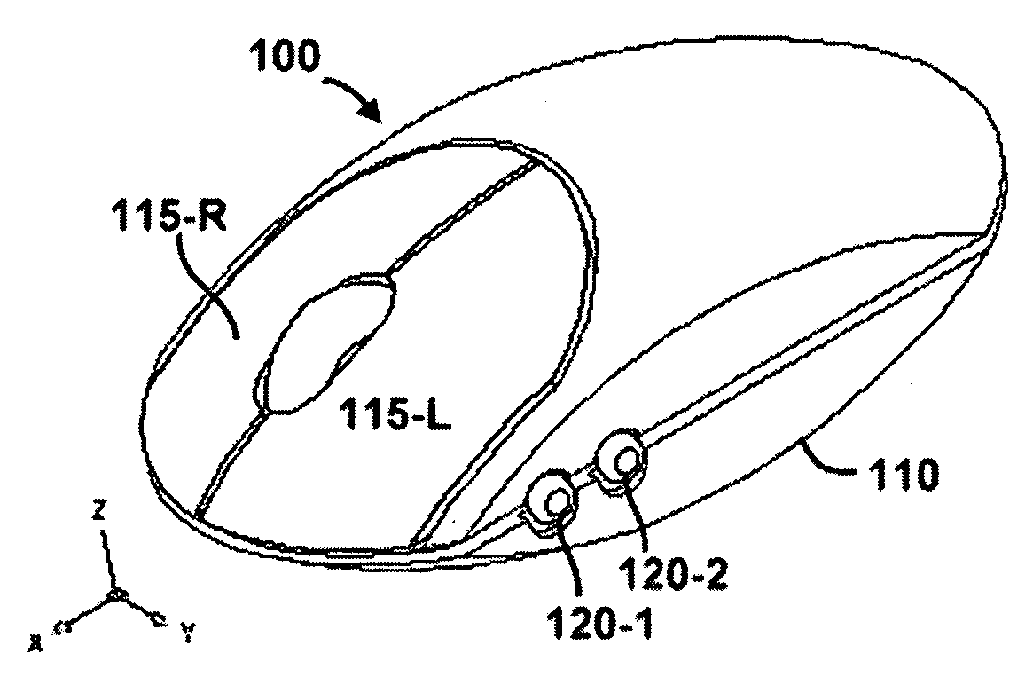
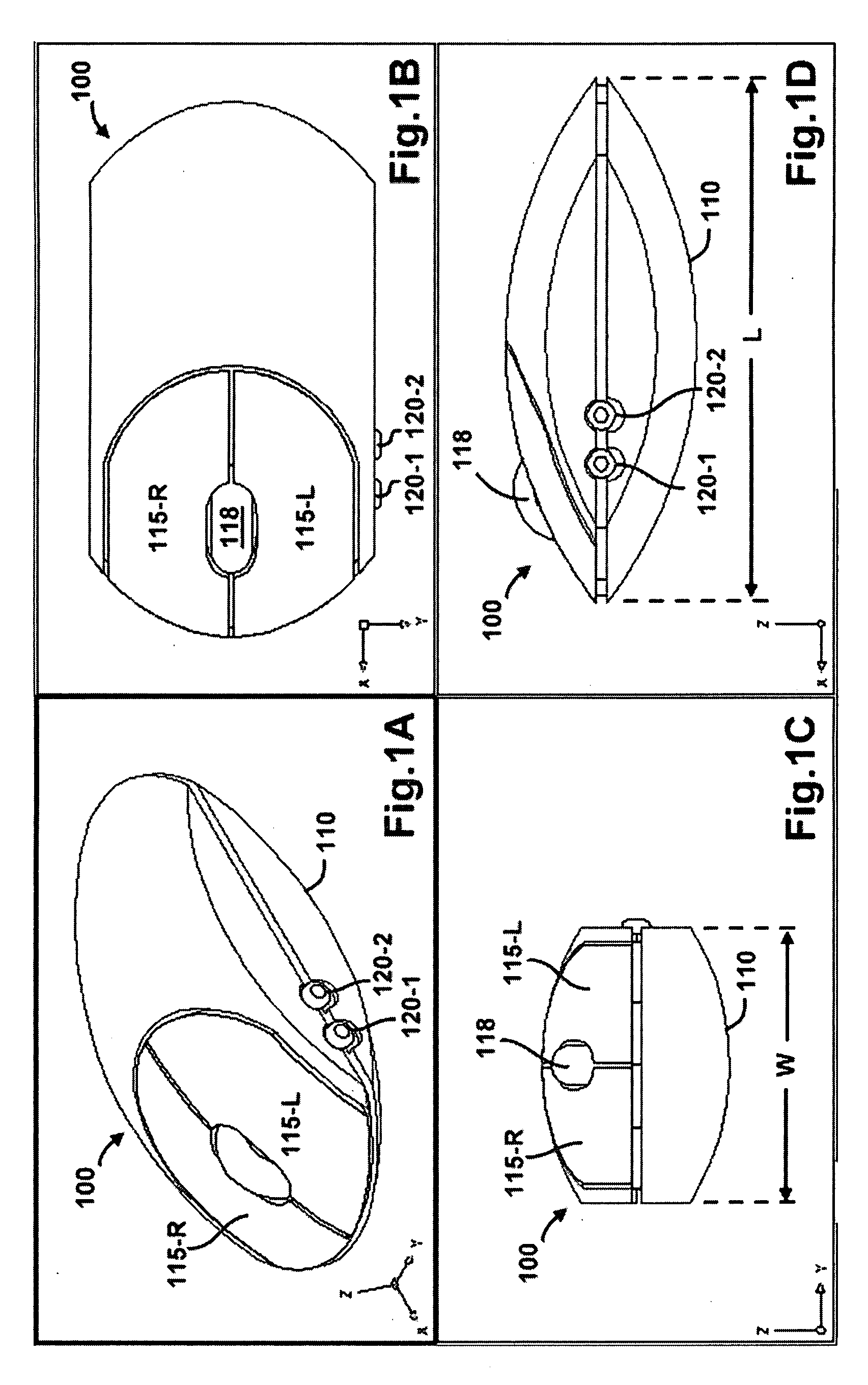
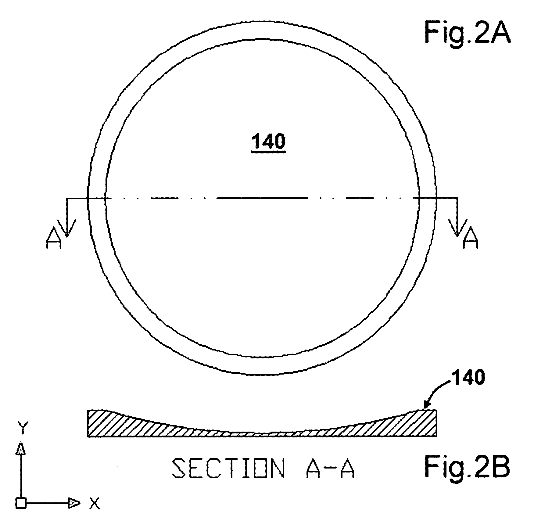
[0020]Please refer to FIGS. 1A to 1D for a perspective view, a top view a front view and a side perspective view of a display cursor control device, i.e., a mouse 100 of the present invention. The display-cursor control device 100 has a curved bottom surface 110 to enhance a movement for conveniently changing the tilt angle of the mouse. The display-cursor control device further includes an accelerometer for sensing a level variation of the mouse. The display cursor-control device such as a computer mouse with a curved bottom surface or a curved mouse pad, the mouse can be convenient tilted to different angles when the mouse or the mouse pad is place on a table. Soon as the mouse is moved to a new tilt angle, the accelerometer detects a level change. In response to the level change, a display cursor is moved on a user graphic interface (GUI) device, e.g., a computer monitor. More specifically, the display-cursor control device 100 as shown further has the following design functions....


PUM


Abstract

A data-handling and processing system includes an image-display cursor-control device for controlling an image display cursor of an image display. The system is further operated a pad for placing and moving the image-display cursor-control device and the pad has a curved surface. The image-display cursor-control device further includes an accelerometer for sensing a tilt angle in moving along the curved surface of the pad. The image-display cursor-control device further includes a container housing for containing the accelerometer therein. The container housing has a curved bottom surface for conveniently tilting the display-cursor control device to change an elevation level of the accelerometer

Description

[0001]This Formal Application claims a Priority Date of Oct. 30, 2006 benefited from a Provisional Patent Applications 60 / 855,718 filed by an Applicant as one of the Inventors of this Application. The disclosures made in Patent Application 60 / 855,718 are hereby incorporated by reference in this Application.BACKGROUND OF THE INVENTION[0002]1. Field of the Invention[0003]This invention relates generally to a display cursor-control device such as a computer mouse for graphic user interface (GUI). More particularly, this invention relates to an improved cursor control device includes an accelerometer configured with a curves shaped bottom surface or a curved shaped pad to enhance a multiple dimensional tilt angle control of a display cursor.[0004]2. Description of the Prior Art[0005]Majority of conventional display cursor-control devices, e.g., computer mouse, is implemented with either optical movement sensing or measurements of the ball rolling movements. Such devices are however limi...

Claims


Application Information

Patent Timeline
Patent Type & Authority Applications(United States)
IPC IPC(8): G06F3/033
CPCG06F3/03543
Inventor LOU, RUEY-DERLIAO, JUNG-HUANGYU, WEN-HSIUNG
Owner IMU SOLUTIONS
Why Eureka
Try Eureka