
Asymmetric multiple constant radii of curvature convex mirrors

a convex mirror and multiple constant radii technology, applied in the field of convex mirrors, can solve the problems of difficult monitoring for drivers, difficult to follow and carefully monitor drivers, and prior art mirrors that have not been optimized to fully accommodate these differences, so as to improve the definition of images and increase the size

Active Publication Date: 2008-05-01
ROSCO
View PDF18 Cites 22 Cited by
  • Summary
  • Abstract
  • Description
  • Claims
  • Application Information

AI Technical Summary

Benefits of technology

[0015]It is an object of the present invention to overcome the aforementioned drawbacks of the prior art and to provide cross-view mirror lenses which generally increase the sizes and improve the definitions of images of children milling about either the front or alongside regions of the school bus. The features of the mirror or mirrors described below are not “required,” but are rather characteristics that may be part of the novel mirror, the exact features and combination of elements being defined by the claims and not by this section of the disclosure.
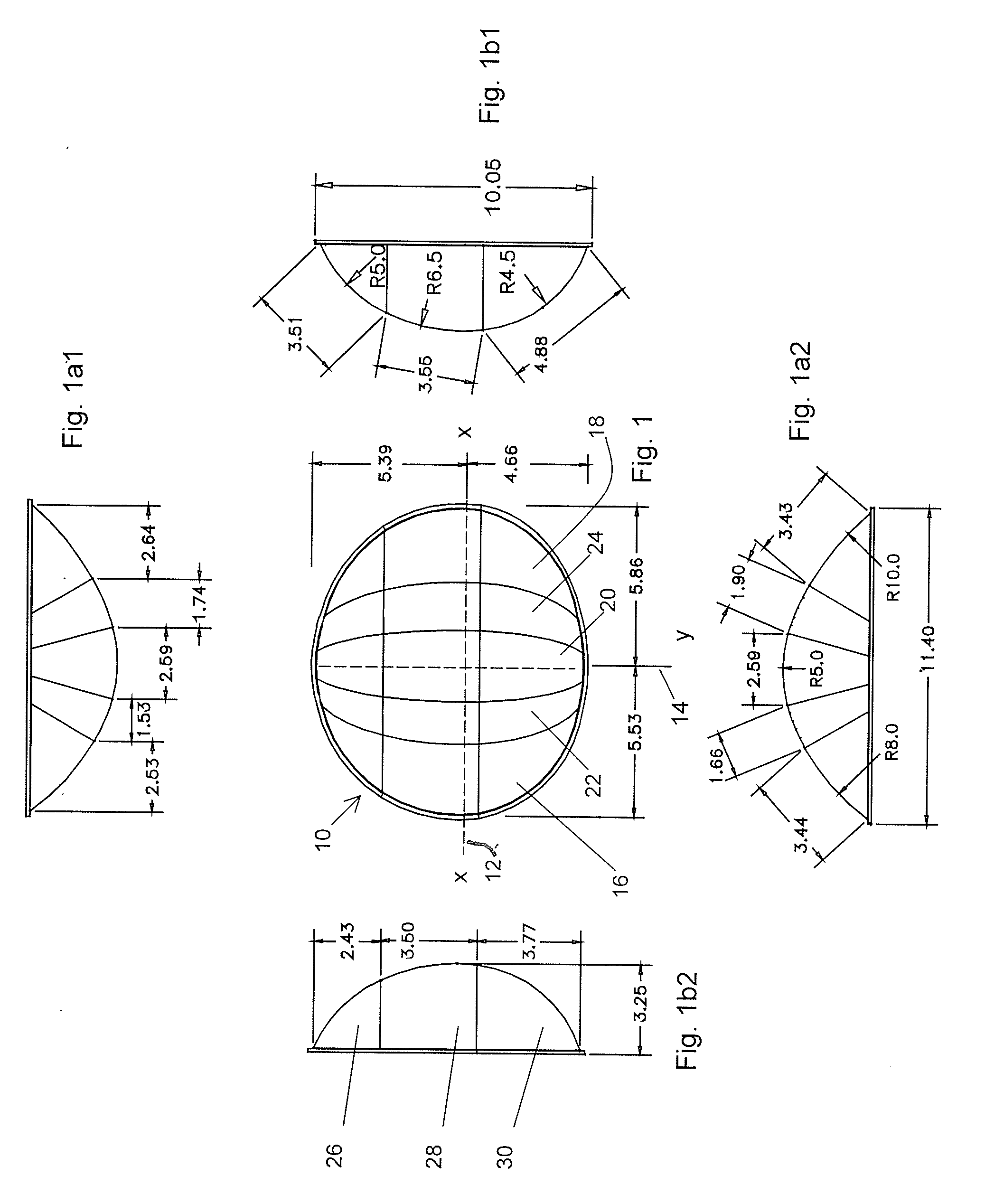
[0016]The foregoing and other objects of the present disclosure are realized by a mirror lens that has a near circular peripheral edge, but, more precisely, a slightly stretched, oblong body characterized in that the right side of the mirror lens, relative to the vertical mounting axis (or the upper peak) of the mirror, has a substantially constant first radius of curvature, and a second substantially constant radius of curvature to the left side of the vertical axis. At the small region in and around the vertical axis, there is a small section of a constant or (optionally) very slightly changing radius of curvature. These regions of constant curvature are bridged by narrow strips of changing curvature mirror surfaces, producing a smoothly changing image size which does not distract or confuse the driver, as an image of a child passes from the right side to the left side of the mirror lens.
[0018]The characteristics of the convex lens are such that the distance from the y-axis to the right edge of the mirror (at the peripheral edge) is not equal to the distance from the y-axis to the left edge of the mirror, producing an asymmetric lens surface, unlike any lens surface of the prior art. Similarly, the mirror is asymmetric in the vertical direction, whereby the distance from the x-axis to the bottom edge of the mirror is different from the distance from the x-axis to the top edge of the mirror along the height direction. Optionally, the effect along the height direction is such that images which are reflected from higher elevations, such as the horizon around the bus and the flashing lights of the school bus, are rendered in smaller size, as they are less important than the images that are located closer to the ground, where the images of children milling about the bus need to be clearly discerned.
[0020]Proceeding vertically, the mirror lens similarly has three, sequentially constant sections of radii of curvature, which are optionally joined by regions of step-wise changing radii of curvature. In accordance with one embodiment, the radius of curvature at the top of the mirror along the y-axis is substantially smaller than the other radii of curvature, to obtain a mirror of substantially reduced height and footprint.
[0022]As another option, the mirror may include a marking visually indicating its peak, namely apogee, and its apex, i.e., the highest point of its dome over the base, thereby assisting or enabling the driver to horizontally align the mirror. The marking can be in the form of darker tinting applied to the mirror at those locations. In addition the mirror may be tinted to reduce glare, preferably along the upper one-third horizontal sector along the y-axis. The tinting may also be applied as a strip of tint extending down along the y-axis, reaching as far down as about two-thirds of the mirror surface. The strip's width may be such that a majority of the image of the bus in the mirror is covered by darker tinting, to further improve the mirror vis-à-vis its sun or headlight glare characteristics.

Problems solved by technology

Prior art mirrors have not been optimized to fully accommodate these differences.
This makes it more difficult for the driver to follow and carefully monitor the movements of a child alongside or in front of the school bus.

Method used


Image

  • Asymmetric multiple constant radii of curvature convex mirrors
  • Asymmetric multiple constant radii of curvature convex mirrors
  • Asymmetric multiple constant radii of curvature convex mirrors

Examples


Embodiment Construction

[0040]With reference to the drawings, the features of and a method for constructing the lens for the present disclosure, which is intended to be known as the EYEMAX mirror lens, are described below.

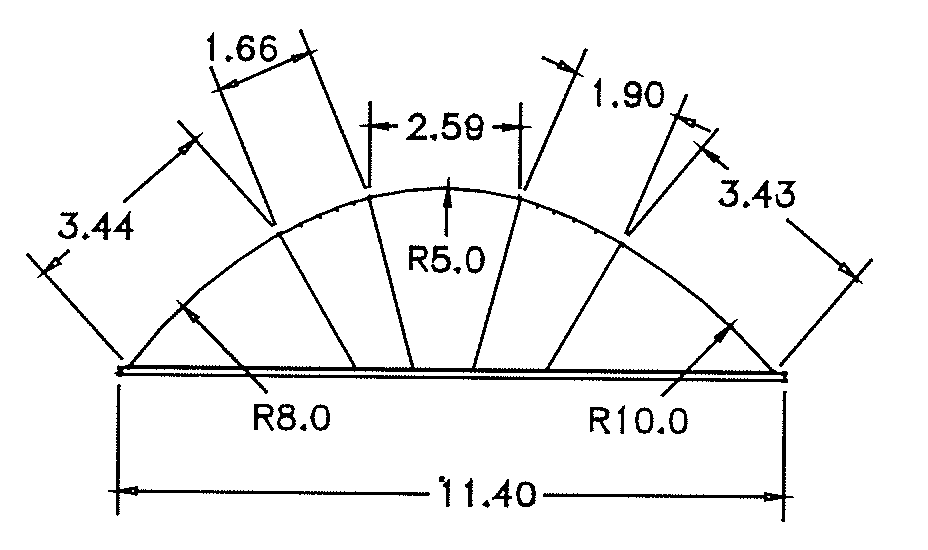
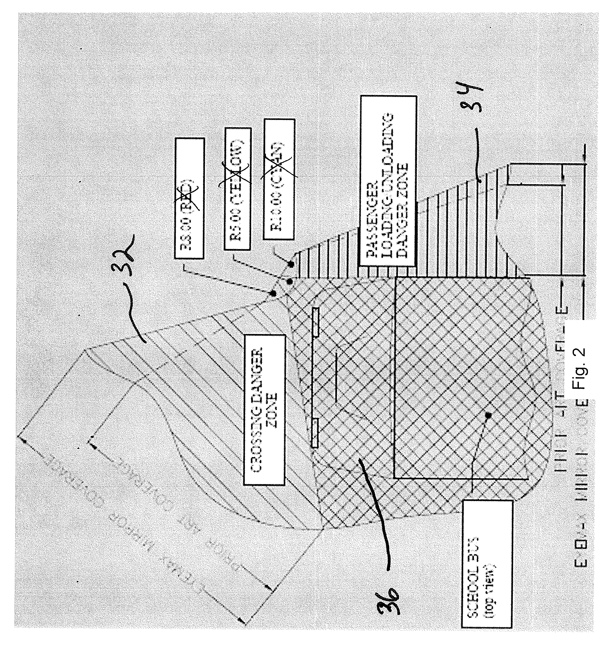
[0041]Construction is based on a multiple, (three) constant radii profile. The same profile is revolved three times to create three sections (slices) with different curvatures, each slice being characterized by a distinct radius of revolution. These sections are joined by intermediate sections that are characterized by having step-wise changing radii of curvature.[0042]The first “slice” is created by revolving an identical profile about a given radius, e.g., R5.00″, denoting a constant radius of curvature of five inches. [0043]The second “slice” is created by revolving an identical profile about a radius R10.00″. [0044]The third “slice” is created by revolving an identical profile about a radius R8.00″.

[0045]All three “slices” (shown above in different shades) are joined (by the regions ...


PUM


Abstract

An asymmetrical mirror lens, usable on front fenders of school buses and similar vehicles, which has a plurality of mirror sections, each having a distinct constant radius of curvature to reduce image distortion. Optional sections located between sections of the constant radius of curvature have a step-wise changing radii of curvature to smooth the image sizes as an object moves across the mirror lens.

Description

CROSS-REFERENCE TO RELATED APPLICATION[0001]The present application claims benefit of and priority to U.S. Provisional Patent Application No. 60 / 855,779 entitled ASYMMETRIC MULTIPLE CONSTANT RADII OF CURVATURE CONVEX MIRRORS filed Nov. 1, 2006, the entire contents of which are hereby incorporated by reference herein.BACKGROUND OF THE INVENTION[0002]This disclosure generally relates to convex, three dimensional mirrors and, more particularly, to a mirror, sometimes referred to as a “cross-over” or “cross-view” mirror, which affords a bus driver, for example, a school bus driver, visual access in front of, as well as alongside the bus. Such cross-over mirrors can however also be used at the rear or front corners of other vehicles such as with trucks, mail vans and the like. More specifically, the present disclosure relates to non-ellipsoidal, asymmetric cross-view mirrors which are optimized to produce more distinct images of objects located in front of or alongside a school bus or si...

Claims


Application Information

Patent Timeline
IPC IPC(8): G02B5/10
CPCB60R1/082B60R1/08B60R1/002B60R1/06B60R1/0605B60R1/10G02B5/10
Inventor ENGLANDER, BENJAMINSERER, JULIAN
Owner ROSCO
Learn More