

Color reproduction correction circuit and correction method
- Summary
- Abstract
- Description
- Claims
- Application Information
AI Technical Summary
Benefits of technology
Problems solved by technology
Method used
Image

Examples
Embodiment Construction
[0038]The embodiments of the invention will be described by referring to the figures as follows.
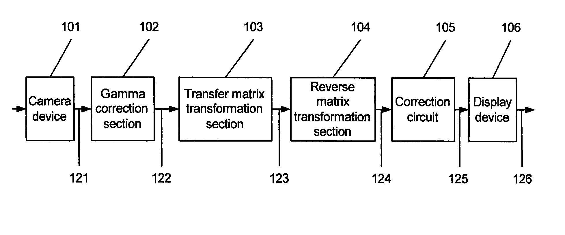
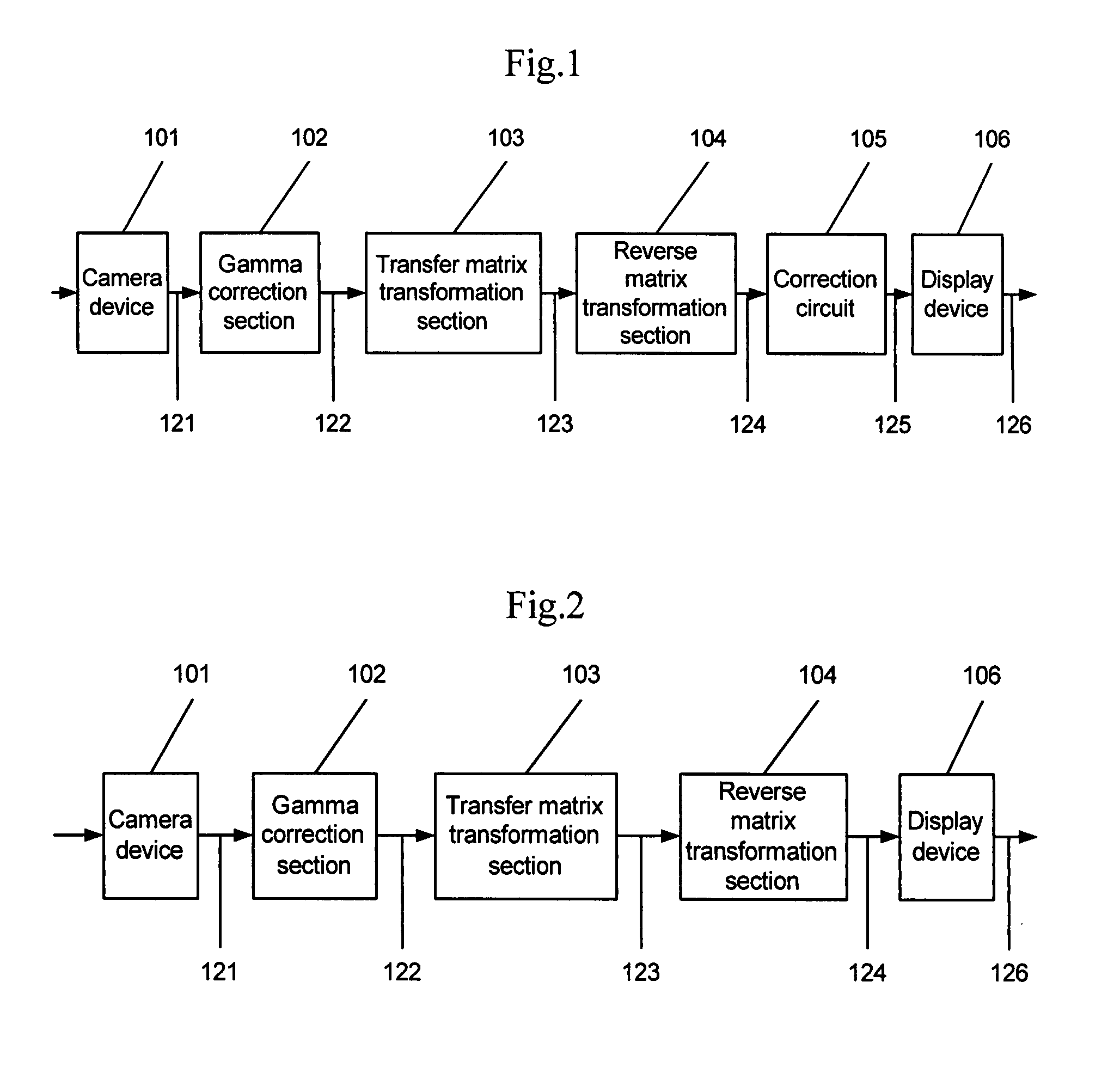
[0039]FIG. 1 shows a schematic block diagram of a color reproduction correction circuit and an image processing system for transmitting and receiving the video signal and displaying the images according to one or more aspects of the invention.
[0040]As shown in FIG. 1, 101 is a camera device, 102 is a gamma correction section, 103 is a transfer matrix transformation section, 104 is a reverse matrix transformation section, 105 is a correction circuit relating to the invention, 106 is a display device, 121 is a R1G1B1 signal which is taken by the camera device 101, 122 is a R1γG1γB1γ signal which is a gamma corrected R1G1B1 signal 121, 123 is a signal which is positioned to follow a brightness signal (Hereinafter referred to as Y) and two color-difference signals (Hereinafter referred to as U, V) transformed from a R1γG1γB1γ signal 122 by the transfer matrix transformation section 103, 124 i...
PUM
 Abstract
Description
Claims
Application Information