Blade/disk dovetail backcut for blade/disk stress reduction (7FA, stage 2)

a technology of disk dovetail and blade, which is applied in the direction of liquid fuel engines, vessel construction, marine propulsion, etc., can solve the problems of not optimizing the location and removal amount of removed materials, potentially life-limiting locations between the blade dovetails and the dovetail slots, etc., to achieve the effect of reducing stress, maintaining or improving the aeromechanical behavior of the turbine blade, and maximizing balan

Inactive Publication Date: 2008-05-01
GENERAL ELECTRIC CO
View PDF11 Cites 14 Cited by
  • Summary
  • Abstract
  • Description
  • Claims
  • Application Information

AI Technical Summary

Benefits of technology

[0005]The present application thus describes a method for reducing stress on at least one of a turbine disk and a turbine blade, wherein a plurality of turbine blades are attachable to the disk, and wherein each of the turbine blades includes a blade dovetail engageable in a correspondingly-shaped dovetail slot in the disk. The method may include: (a) determining a start point for a dovetail backcut relative to a datum line, the start point defining a length of the dovetail backcut along a dovetail axis; (b) determining a cut angle for the dovetail backcut; and (c) removing material from at least one of the blade dovetail or the disk dovetail slot according to the start point and the cut angle to form the dovetail backcut. The start point and the cut angle may be optimized according to blade and disk geometry to maximize a balance between stress reduction on the disk, stress reduction on the blade, a useful life of the turbine blades, and maintaining or improving the aeromechanical behavior of the turbine blade. The datum line may be positioned a fixed distance from a forward face of the blade dovetail along a centerline of the dovetail axis, and step (a) may be practiced such that the start point of the dovetail backcut is at least approximately 1.215 inches in an aft direction from the datum line.
[0008]The present application further describes a turbine blade that may include an airfoil and a blade dovetail, the blade dovetail being shaped corresponding to a dovetail slot in a turbine disk. The blade dovetail may include a dovetail backcut sized and positioned according to blade geometry to maximize a balance between stress reduction on the disk, stress reduction on the blade, a useful life of the turbine blade, and maintaining or improving the aeromechanical behavior of the turbine blade. A start point of the dovetail backcut, which defines a length of the dovetail backcut along a dovetail axis, may be determined relative to a datum line positioned a fixed distance from a forward face of the blade dovetail along a centerline of the dovetail axis. The start point of the dovetail backcut may be at least approximately 1.215. inches in an aft direction from the datum line.

Problems solved by technology

It has been found that interface locations between the blade dovetails and the dovetail slots are potentially life-limiting locations due to overhanging blade loads and stress concentrating geometry.
Moreover, the locations and removed material amounts were not optimized to maximize a balance between stress reduction on the disk, stress reduction on the blades, and a useful life of the blades.

Method used


Image

  • Blade/disk dovetail backcut for blade/disk stress reduction (7FA, stage 2)
  • Blade/disk dovetail backcut for blade/disk stress reduction (7FA, stage 2)
  • Blade/disk dovetail backcut for blade/disk stress reduction (7FA, stage 2)

Examples


Embodiment Construction

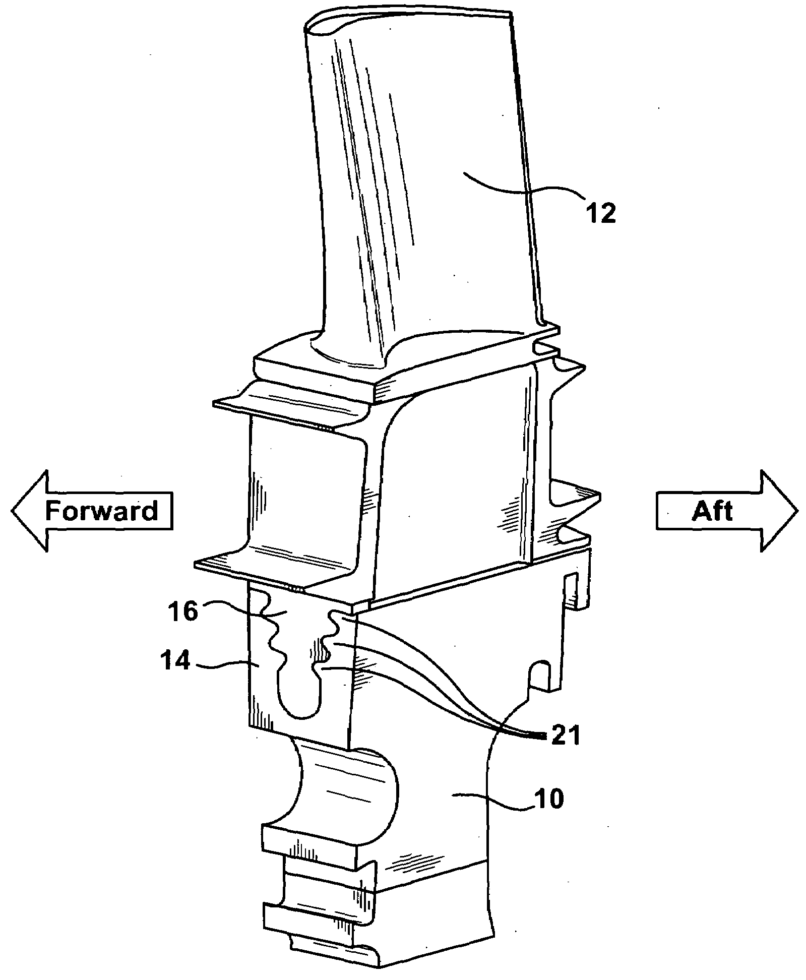
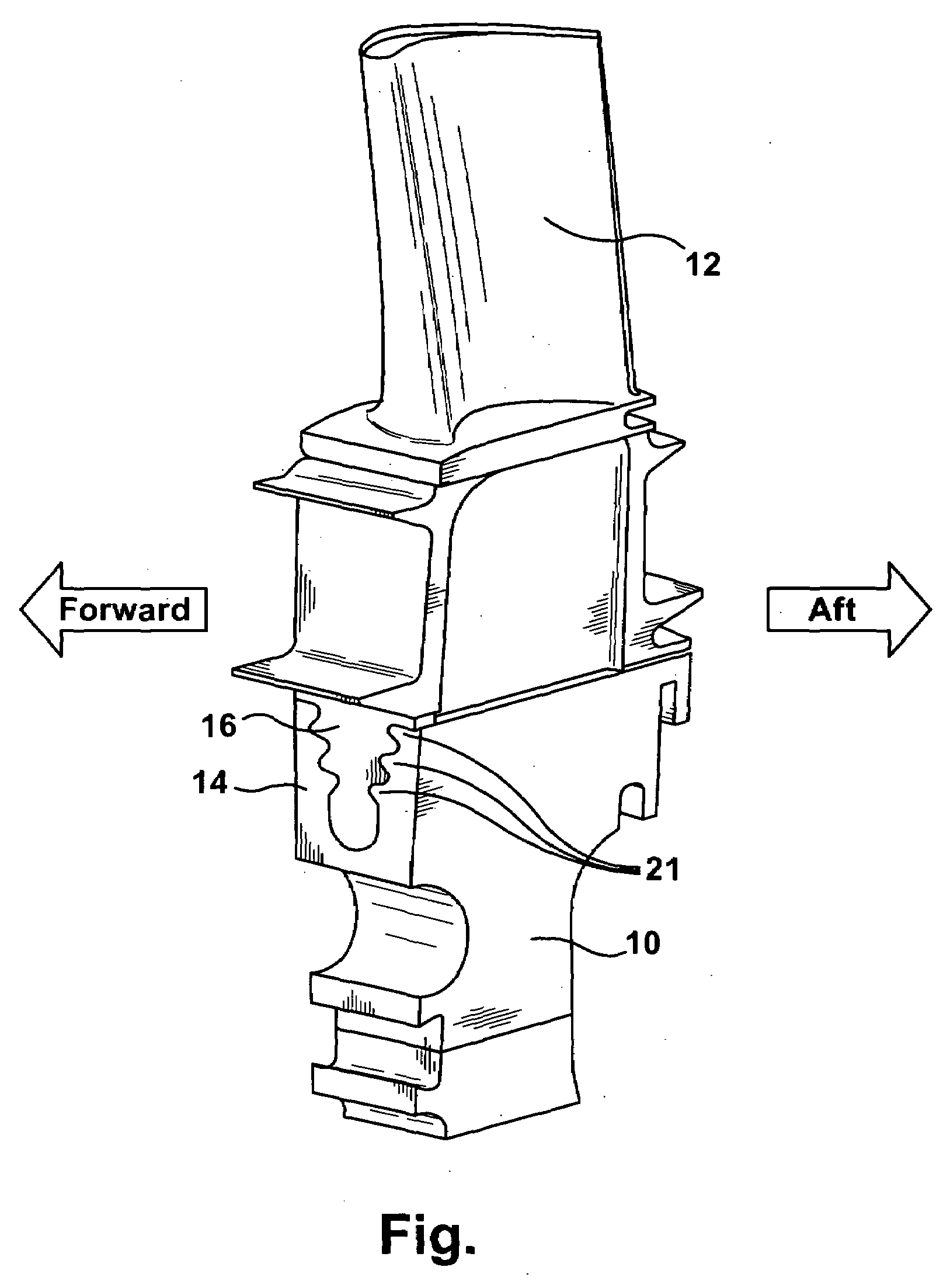
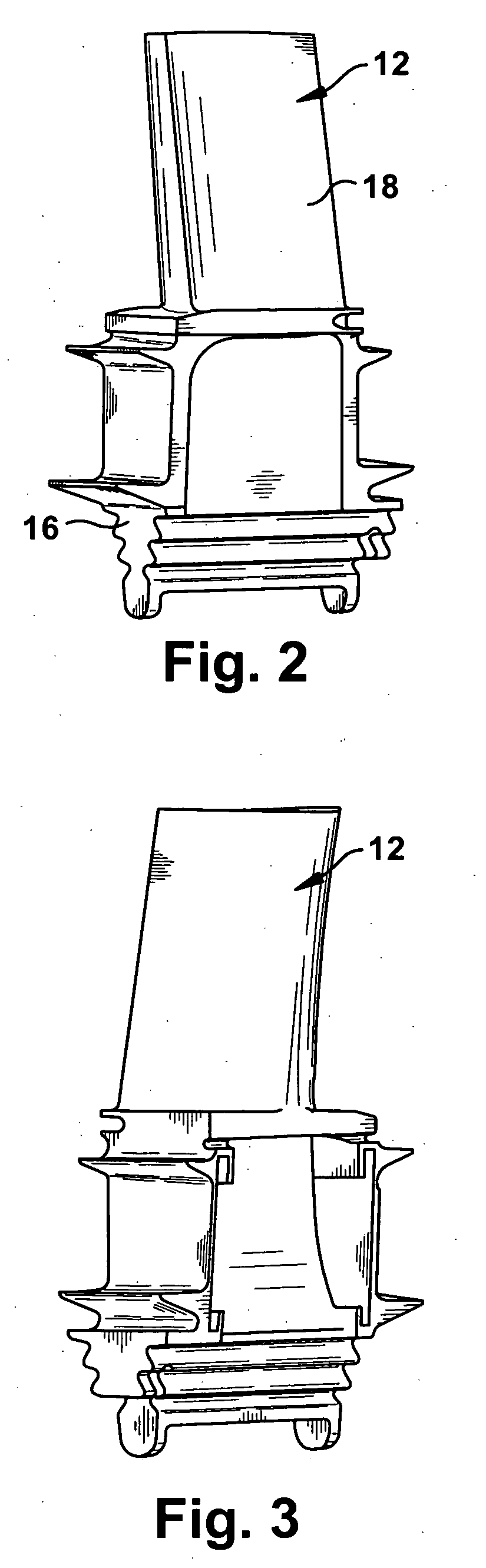
[0029]FIG. 1 is a perspective view of an exemplary gas turbine disk segment 10 in which is secured a gas turbine blade 12. The gas turbine disk 10 includes a dovetail slot 14 that receives a correspondingly shaped blade dovetail 16 to secure the gas turbine blade 12 to the disk 10. FIGS. 2 and 3 show opposite sides of a bottom section of the gas turbine blade 12 including an airfoil 18 and the blade dovetail 16. FIG. 2 illustrates a so-called pressure side of the gas turbine blade 12, and FIG. 3 illustrates a so-called suction side of the gas turbine blade 12.

[0030]The dovetail slots 14 are typically termed “axial entry” slots in that the dovetails 16 of the blades 12 are inserted into the dovetail slots 14 in a generally axial direction, i.e., generally parallel but skewed to the axis of the disk 10.

[0031]An example of a gas turbine disk stress concentrating feature is the cooling slot. The upstream or downstream face of the blade and disk 10 may be provided with an annular cooling...


PUM


Abstract

A turbine blade that may include an airfoil and a blade dovetail, the blade dovetail being shaped corresponding to a dovetail slot in a turbine disk. The blade dovetail may include a dovetail backcut sized and positioned according to blade geometry to maximize a balance between stress reduction on the disk, stress reduction on the blade, a useful life of the turbine blade, and maintaining or improving the aeromechanical behavior of the turbine blade. A start point of the dovetail backcut, which defines a length of the dovetail backcut along a dovetail axis, may be determined relative to a datum line positioned a fixed distance from a forward face of the blade dovetail along a centerline of the dovetail axis. The start point of the dovetail backcut may be at least approximately 1.215 inches in an aft direction from the datum line.

Description

BACKGROUND OF THE INVENTION[0001]The present invention relates to gas turbine technology and, more particularly, to a modified blade and / or disk dovetail designed to divert the blade load path around a stress concentrating feature in the disk on which the blade is mounted and / or a stress concentrating feature in the blade itself.[0002]Certain gas turbine disks include a plurality of circumferentially spaced dovetails about the outer periphery of the disk defining dovetail slots therebetween. Each of the dovetail slots receives in an axial direction a blade formed with an airfoil portion and a blade dovetail having a shape complementary to the dovetail slots.[0003]The blades may be cooled by air entering through a cooling slot in the disk and through grooves or slots formed in the dovetail portions of the blades. Typically, the cooling slot extends circumferentially 360° through the alternating dovetails and dovetail slots.[0004]It has been found that interface locations between the ...

Claims


Application Information

Patent Timeline
Patent Type & Authority Applications(United States)
IPC IPC(8): F01D5/30
CPCF01D5/3015
Inventor ZEMITIS, WILLIAMBYAM, STEVEMOHR, PATRICK
Owner GENERAL ELECTRIC CO
Why Eureka
Try Eureka