
Active vibration reduction system

a technology of active vibration and reduction system, which is applied in the direction of shock absorbers, machine supports, mechanical equipment, etc., can solve the problems of noise issue, difficulty in perception for pedestrians and the like,

Inactive Publication Date: 2008-05-08
AISIN SEIKI KK
View PDF1 Cites 35 Cited by
  • Summary
  • Abstract
  • Description
  • Claims
  • Application Information

AI Technical Summary

Benefits of technology

[0006]According to an aspect of the present invention, an active vibration reduction system for a vehicle for suppressing a vibration from a vibration source includes a vibration suppression signal generating unit for generating a vibration suppression signal having a frequency being synchronous with the vibration from the vibration source, a sensible signal generating unit for generating a

Problems solved by technology

However, it becomes difficult for pedestrians and the like to perceive the approach of the vehicle in exchange for improvement of the vibration suppression performance.
However, if the car horn is sounded while the vehicle is being driven in an urban area or a residential area, other issues such as a noise issue may occur.

Method used


Image

  • Active vibration reduction system
  • Active vibration reduction system
  • Active vibration reduction system

Examples


first embodiment

of the Present Invention

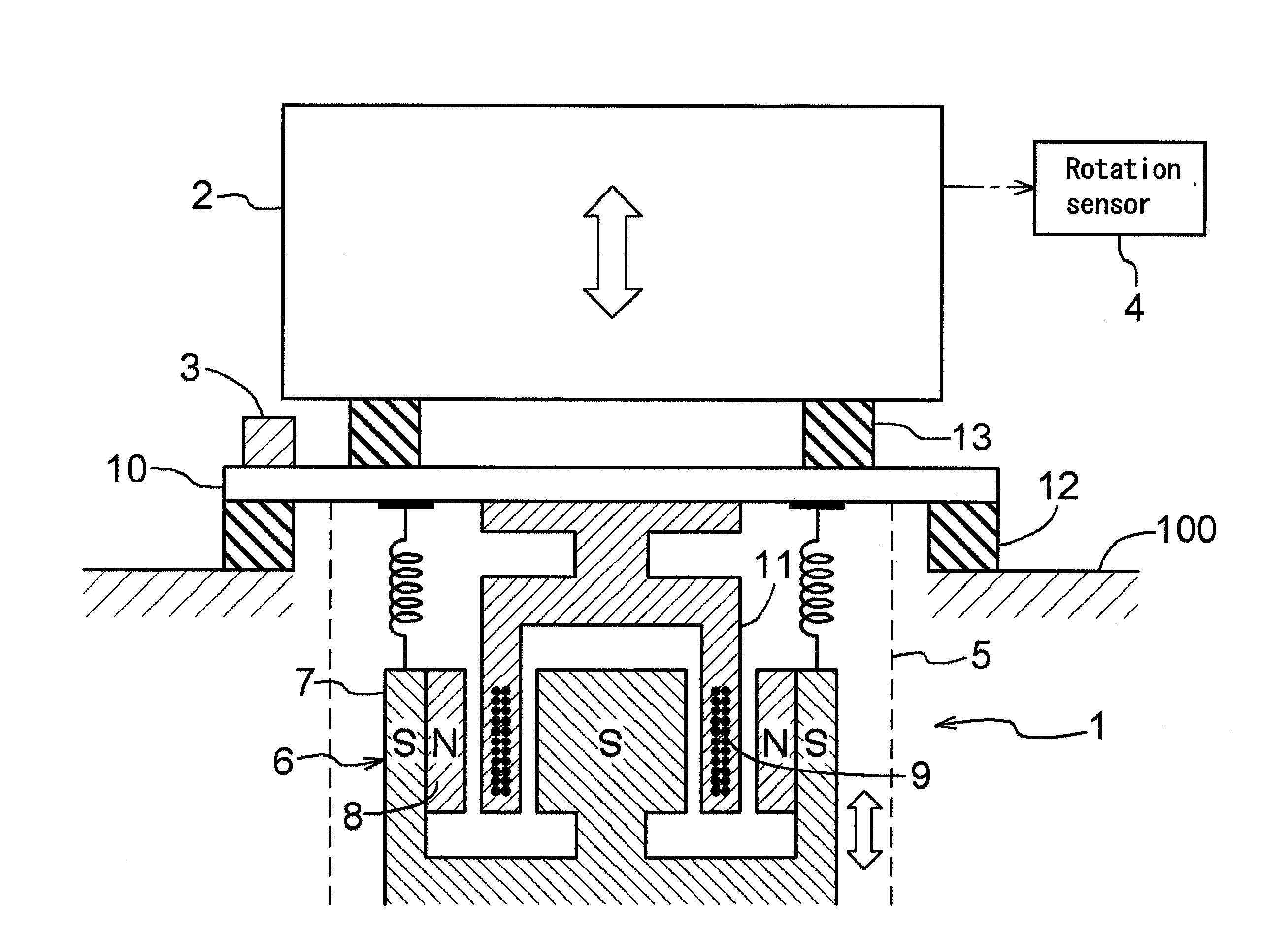
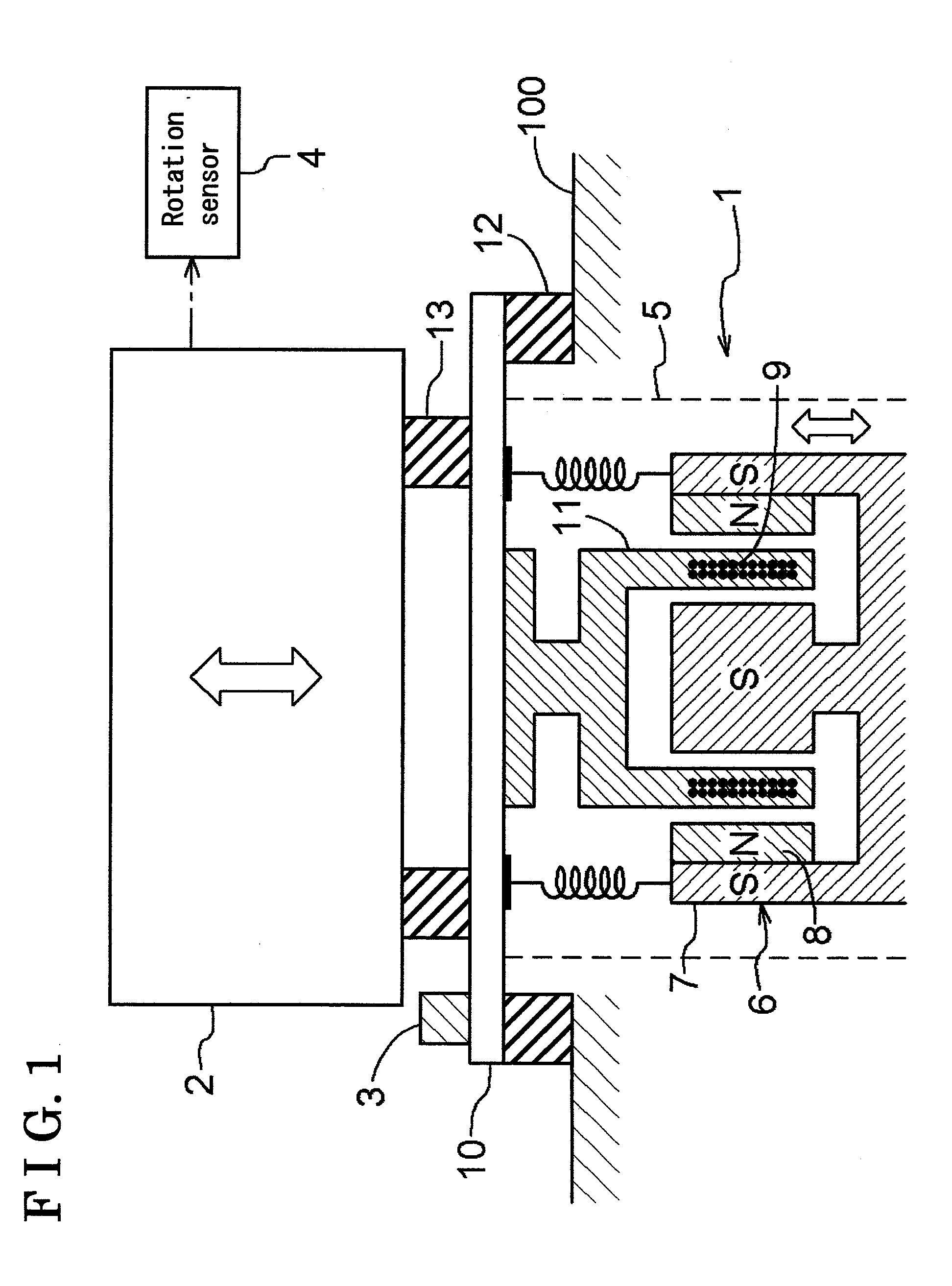
[0019]FIG. 1 is a schematic view illustrating an arrangement of an active vibration reduction system 1. The active vibration reduction system 1 according to the embodiments of the present invention is provided with a vibrator 5 for actively suppressing or reducing vibrations of an engine 2, i.e. a vibration source, by providing vibrations to the engine 2 included at a vehicle. The vibrator 5 is provided with a magnetic pole 6 and a coil 9 which is provided thereat so as to intersect magnetic flux formed by the magnetic pole 6.

[0020]The magnetic pole 6 is provided with a south pole 7 and north poles 8, and the coil 9 is movably inserted into a cylindrical space defined between the south pole 7 and the north poles 8. The coil 9 is held by a cylindrical coil holding member 11, and the coil holding member 11 is fixed to an engine sub-flame 10 which is provided at a body 100 via rubber mounts 12. Further, the engine 2 is provided via the engine sub-frame 10 and th...

second embodiment

of the Present Invention

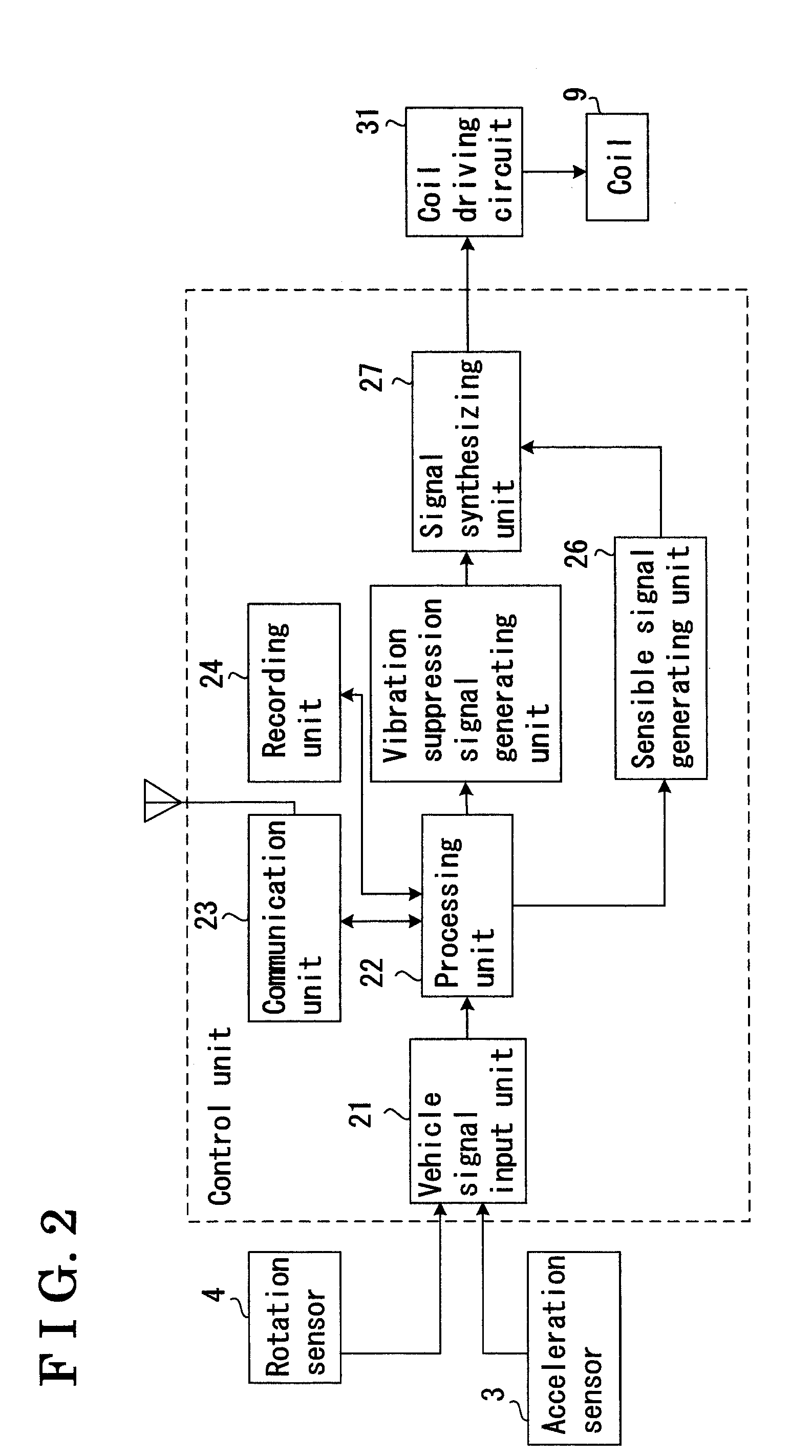
[0030]FIG. 9 is a schematic view showing an entire system of an active vibration reduction system according to a second embodiment of the present invention. The system is different from that of the first embodiment in that an output switching unit 28, a lowpass filter 29, and an audio equipment 30 are provided thereat. In the second embodiment, the coil 9, which is provided at the active vibration reduction system 1, may be vibrated based on an audio signal of the audio equipment 30 provided at an exterior portion of the system. In this case, the audio signal is transmitted from the audio equipment 30 to the coil driving circuit 31 via the lowpass filter 29. Before the audio signal is transmitted to the coil driving circuit 31, the synthesized signal, which is synthesized in the signal synthesizing unit 27, is switched to the audio signal in the output switching unit 28. So configured, the coil 9 provided at the active vibration reduction system 1 is vibrated...


PUM


Abstract

An active vibration reduction system for a vehicle for suppressing a vibration from a vibration source includes a vibration suppression signal generating unit for generating a vibration suppression signal having a frequency being synchronous with the vibration from the vibration source, a sensible signal generating unit for generating a sensible signal having a frequency being asynchronous with the vibration from the vibration source, a magnetic pole forming magnetic flux, a coil provided in a manner that intersects the magnetic flux, and a coil driving circuit relatively vibrating the magnetic pole and the coil by controlling an energized state of the coil based on the vibration suppression signal and the sensible signal.

Description

CROSS REFERENCE TO RELATED APPLICATIONS[0001]This application is based on and claims priority under 35 U.S.C § 119 with respect to Japanese Patent Application 2006-302832, filed on Nov. 8, 2006, the entire content of which is incorporated herein by reference.FIELD OF THE INVENTION[0002]This invention relates to an active vibration reduction system, in particular, the invention relates to an active vibration reduction system which provides vibrations to a vibration source such as a vehicle engine to actively suppress vibrations from the vibration source.BACKGROUND[0003]An active vibration reduction system actively suppresses vibrations occurring when an engine, a motor or the like provided at a vehicle vibrates by providing vibrations, which has a substantially opposite phase of the vibrations of a vibration source, and thus improving comfort and quietness in the vehicle. For example, in an active vibration reduction system disclosed in JP 2001-14097A, an electromagnetic actuator (co...

Claims


Application Information

Patent Timeline
IPC IPC(8): F16F15/03
CPCF16F15/08F16F15/03
Inventor FUSHIMI, TAKEHIKOMIZUSHIMA, DAICHI
Owner AISIN SEIKI KK
Features
  • Generate Ideas
  • Intellectual Property
  • Life Sciences
  • Materials
  • Tech Scout
  • Unparalleled Data Quality
  • Higher Quality Content
  • 60% Fewer Hallucinations
Learn More