
Electrically Programmable Fuse Sense Circuit

Inactive Publication Date: 2008-05-08
IBM CORP
View PDF7 Cites 13 Cited by
  • Summary
  • Abstract
  • Description
  • Claims
  • Application Information

AI Technical Summary

Benefits of technology

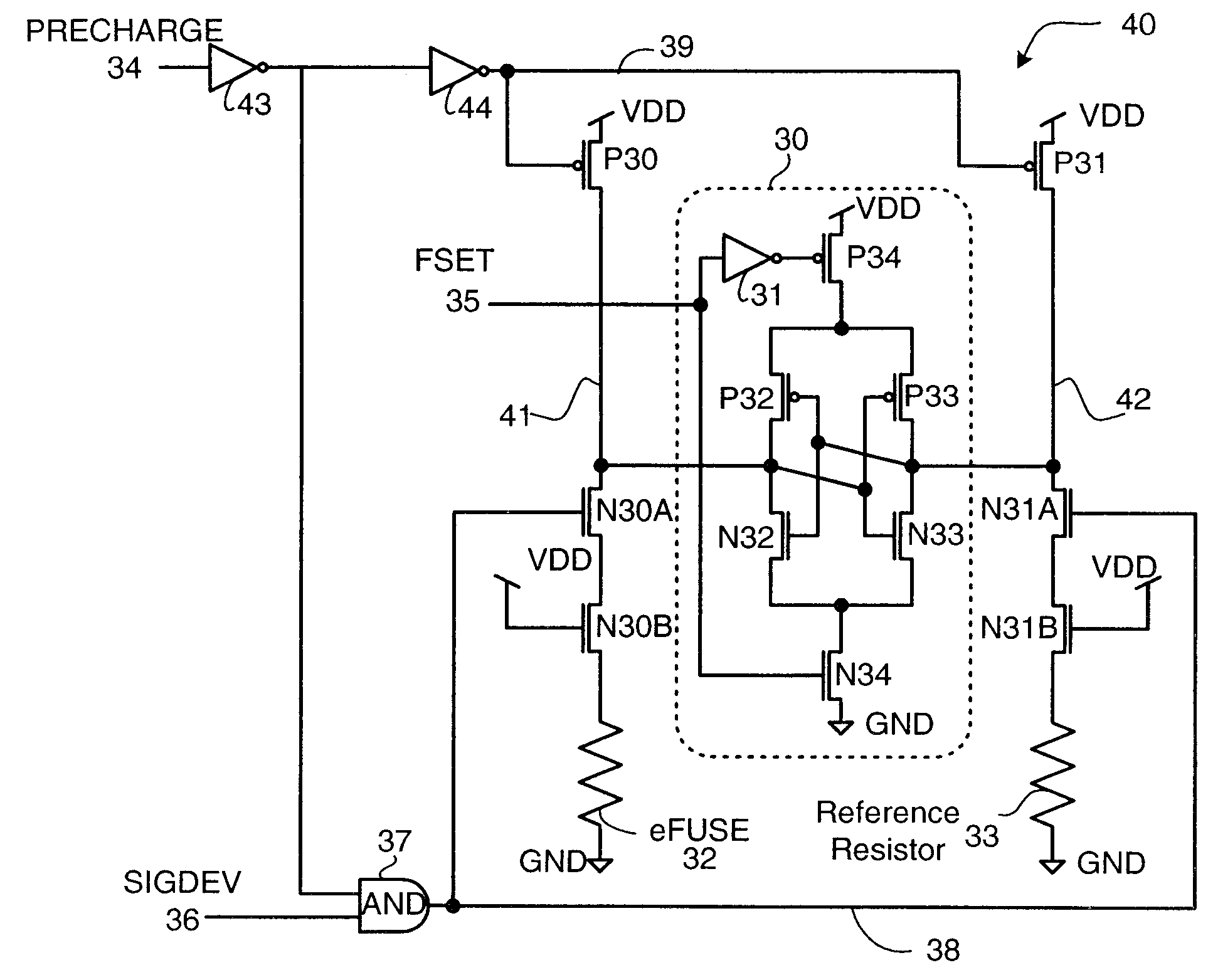
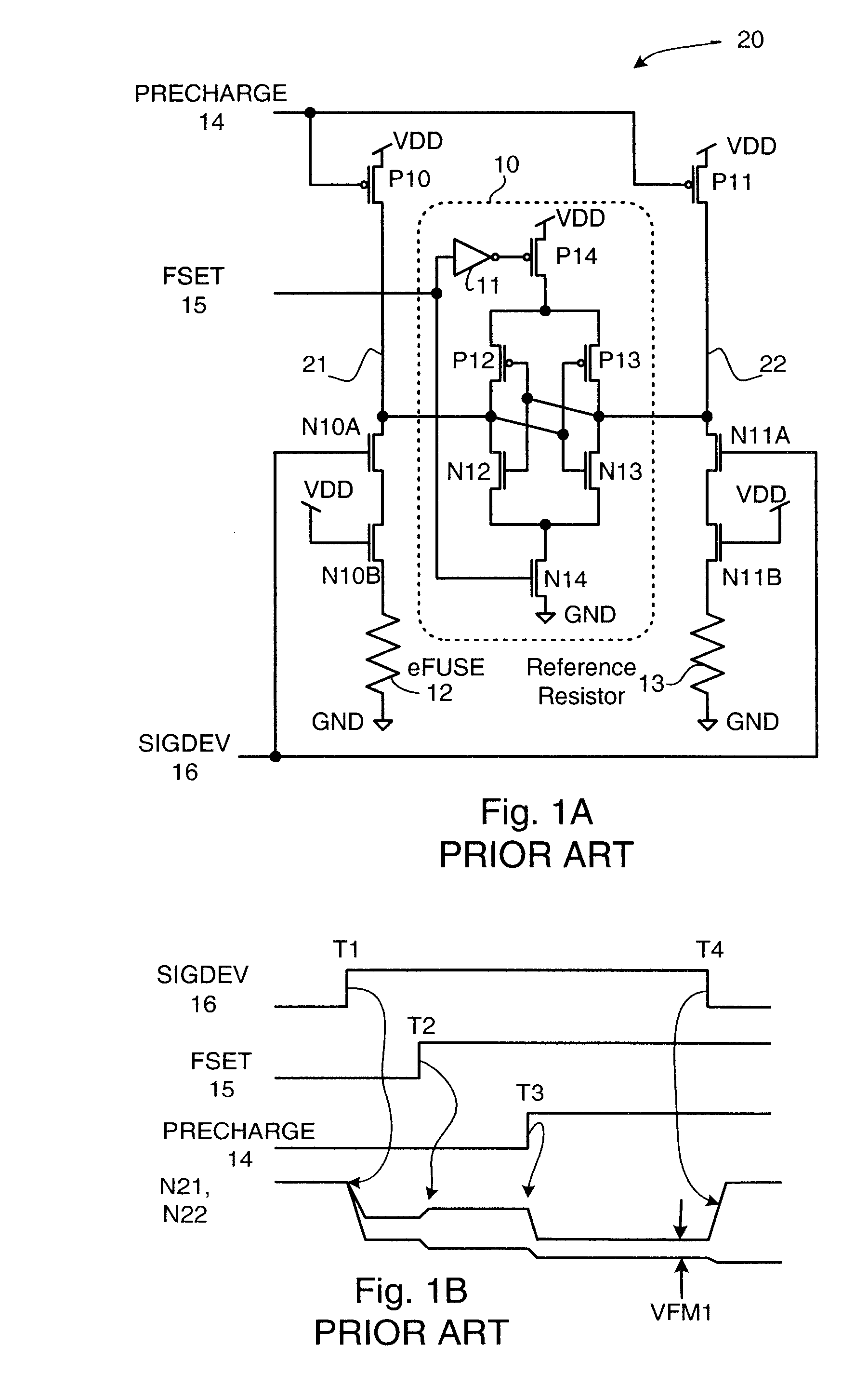
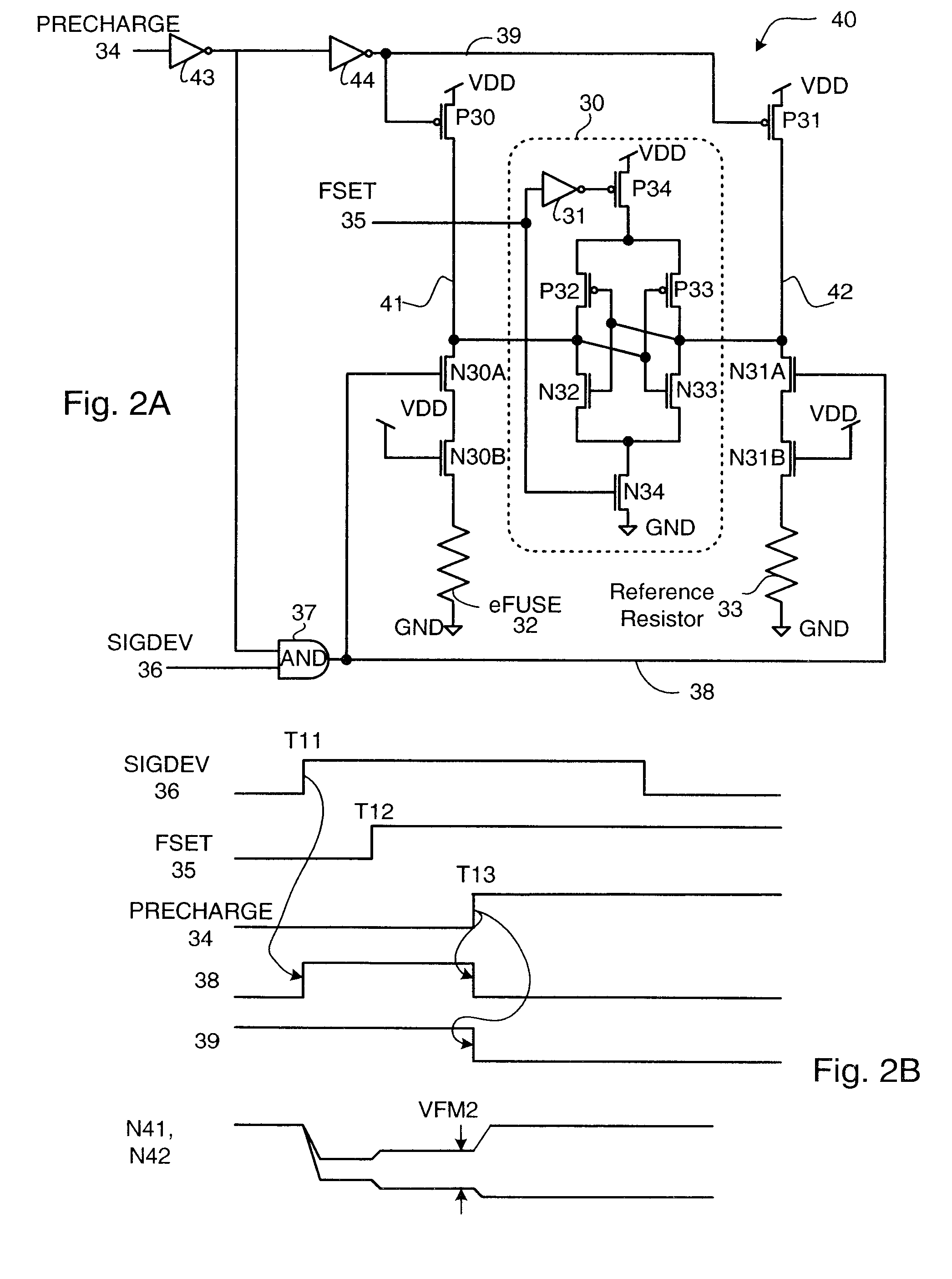
[0020]In an embodiment, the electrically programmable fuse sensing circuit comprises an electrically programmable fuse and a reference resistance, the electrically programmable fuse having less resistance than the reference resistance when the electrically programmable fuse is unblown but the electrically programmable fuse has more resistance than the reference resistance when the electrically programmable fuse is blown. A first current source passes current through a first switch and the electrically programmable fuse, producing an electrically programmable fuse voltage. A second current source passes current through a second switch and the reference resistance, producing a reference voltage. At a latching time, simultaneously the first current source and the second current source are shut off and the first and second switches are opened. The latching circuit latches a logical value responsive to t

Problems solved by technology

An electrically programmable fuse may be blown during manufacturing or may be blown at a later time, for example, in a customer's office.
Second, continuously running current through an electrically programmable fuse may eventually electromigrate the silicide on an electrically programmable fuse, possibly making the electrically programmable fuse appear to be “blown”, even though the electrically programmable fuse has not been blown.

Method used


Image

  • Electrically Programmable Fuse Sense Circuit
  • Electrically Programmable Fuse Sense Circuit
  • Electrically Programmable Fuse Sense Circuit

Examples


Embodiment Construction

[0028]In the following detailed description of the preferred embodiments, reference is made to the accompanying drawings, which form a part hereof, and within which are shown by way of illustration specific embodiments by which the invention may be practiced. It is to be understood that other embodiments may be utilized and structural changes may be made without departing from the scope of the invention.

[0029]The present invention provides an improved apparatus for sensing whether an electrically programmable fuse is blown or unblown.

[0030]In the literature a “blown” electrically programmable fuse is also called a “programmed” electrically programmable fuse. Similarly, an “unblown” electrically programmable fuse is called an “unprogrammed” electrically programmable fuse. The process of blowing a particular electrically programmable fuse is often referred to as programming the particular electrically programmable fuse.

[0031]It will be appreciated that there also exist “antifuse” vers...


PUM


Abstract

A electrically programmable fuse sense circuit having an electrically programmable fuse and a reference resistance. A first current source is coupled, through a first switch, to the electrically programmable fuse. A second current source is coupled, through a second switch, to the reference resistance. A precharge signal enables the first current source, the second current source and closes the first switch and the second switch, creating voltage drops across the electrically programmable fuse and the reference resistance. When the precharge signal goes inactive, the first current source and the second current source are shut off, and, at the same time the first switch and the second switch are opened. A latching circuit uses a difference in the voltage drops when the precharge signal goes inactive to store a state of the electrically programmable fuse, indicative of whether the electrically programmable fuse is blown or unblown.

Description

BACKGROUND OF THE INVENTION[0001]1. Field of the Invention[0002]This invention relates generally to electrically programmable fuse technology, and in particular, to circuitry used to sense whether an electrically programmable fuse is blown or unblown.[0003]2. Description of the Related Art[0004]Modern electronic systems frequently use one or more electrically programmable fuses on a semiconductor chip to personalize function of the semiconductor chip in a particular electronic system. An electrically programmable fuse may be blown during manufacturing or may be blown at a later time, for example, in a customer's office. A state of an electrically programmable fuse (i.e., whether the electrically programmable fuse is “blown” or “unblown”) or of a plurality of electrically programmable fuses is used on the semiconductor chip to enable function, disable function, or to change function of the semiconductor chip. For example, a test function needed to test an electronic function may not ...

Claims


Application Information

Patent Timeline
IPC IPC(8): H01H37/76G01R31/74
CPCG11C17/18G11C17/16
Inventor AIPPERSPACH, ANTHONY GUSALLEN, DAVID HOWARDPAONE, PHILSCHMITT, DAVID EDWARDUHLMANN, GREGORY JOHN
Owner IBM CORP
Learn More