Removal device for micro-bubbles and dirt

Active Publication Date: 2012-07-12
FLAMCO BV
View PDF4 Cites 7 Cited by
  • Summary
  • Abstract
  • Description
  • Claims
  • Application Information

AI Technical Summary

Benefits of technology

[0025]In a further embodiment, a curvature in the edges of the plates near the quiet zone in the direction of the liquid flow is provided, in such a way that the liquid is guided gradually and in a curved manner into the quiet zones and has less resistance.
[0026]The constricted opening can also be provided with a curvature in the direction of the liquid flow, which causes a better guiding of the liquid and a reduction of the resistance. Downstream of the constricted opening,

Problems solved by technology

It was found that the flow in the removal device according to EP0244881A1 has a disadvantageous form.
It w

Method used


Image

  • Removal device for micro-bubbles and dirt
  • Removal device for micro-bubbles and dirt
  • Removal device for micro-bubbles and dirt

Examples


Embodiment Construction

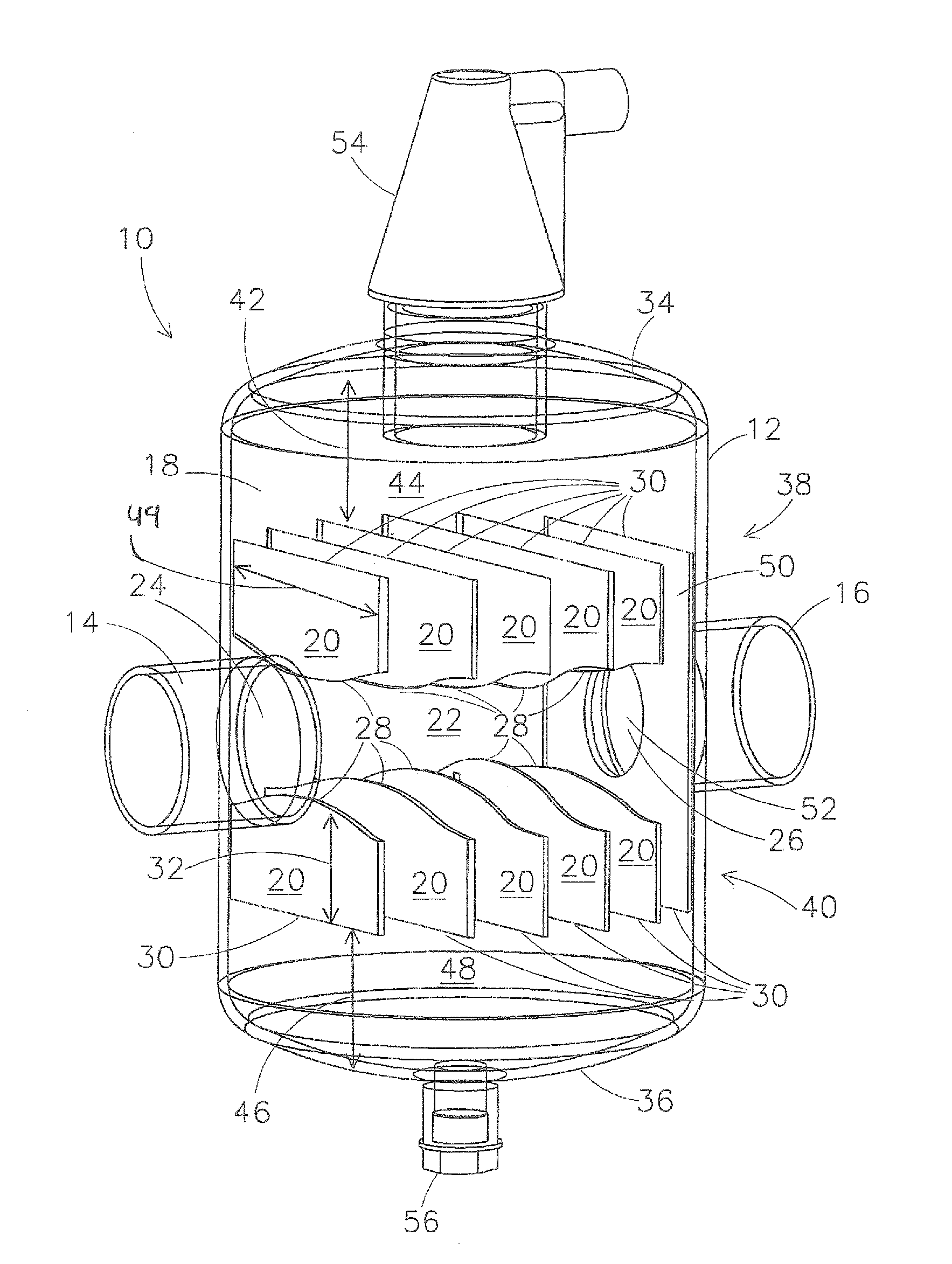
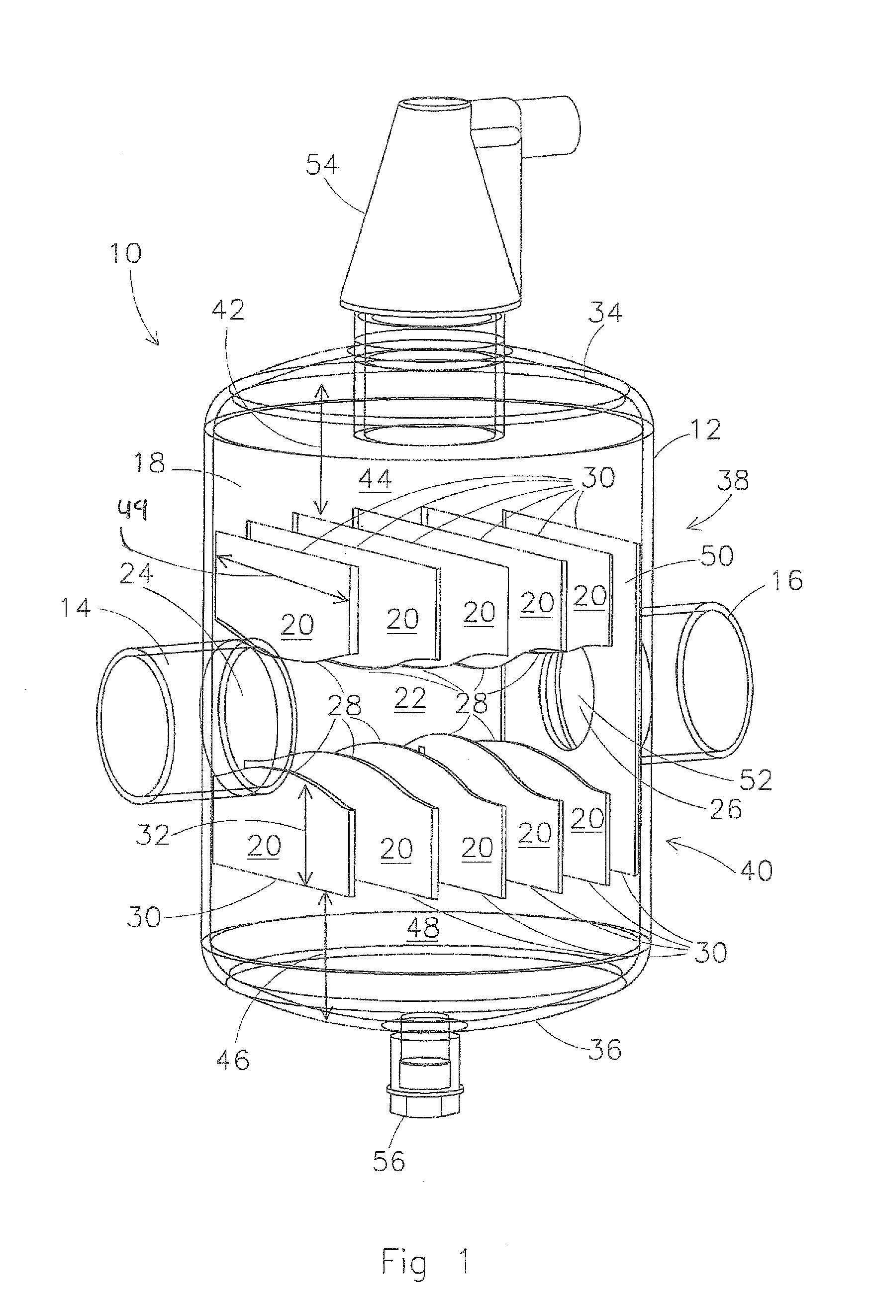
[0041]FIG. 1 shows a removal device 10 with a housing 12 an entry 14 and an exit 16. The entry and the exit are configured to be connected to a conduit system, in such a way that the removal device is provided in-line with the conduit system. A typical conduit system for example is a warm water conduit system of a heating installation.

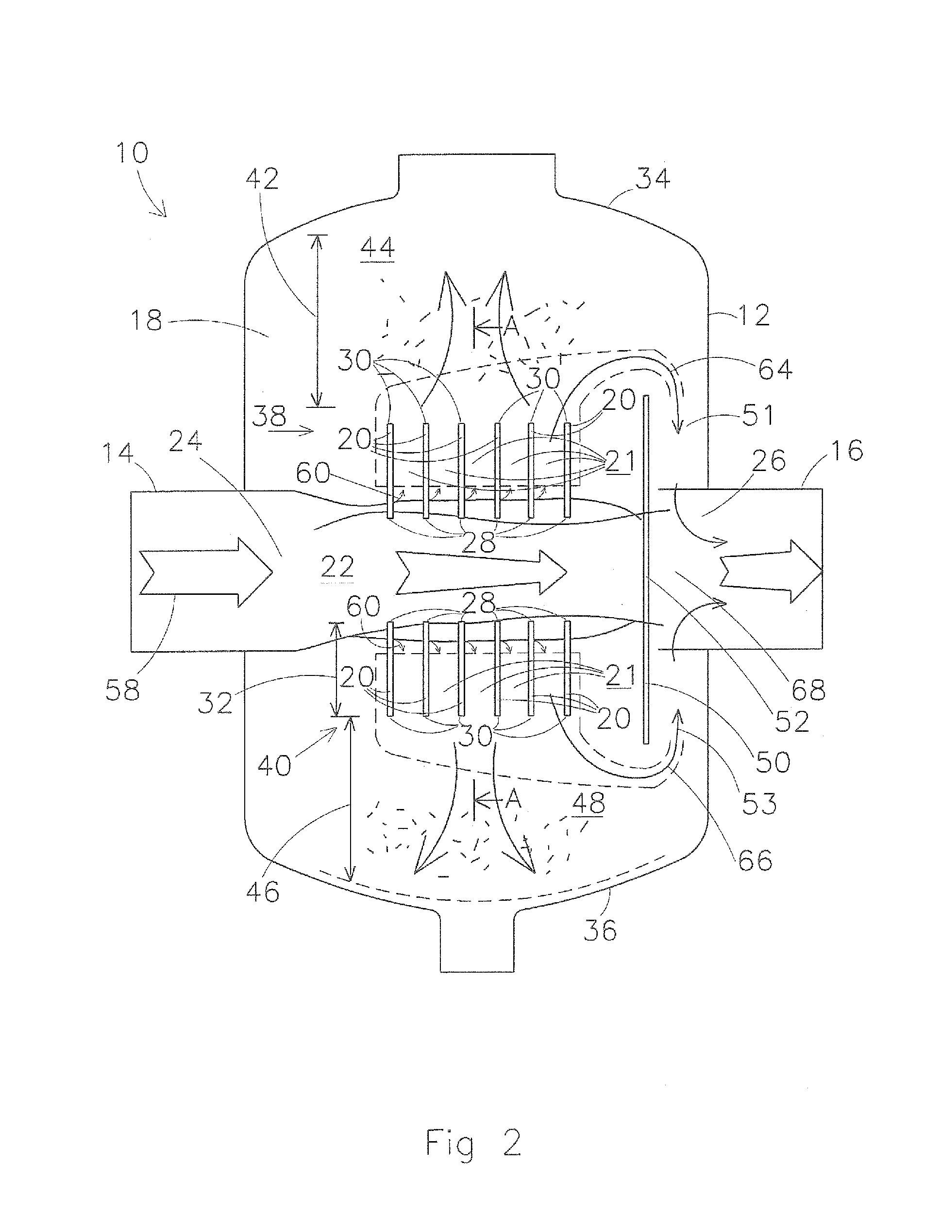
[0042]The housing 12 defines an inner space 18 with a certain volume. A number of plates 20 are provided in the housing 12. The plates 20 extend substantially laterally to the direction of flow. In a different embodiment, the plates can also be provided at a slight angle to a transverse direction of flow. The plates 20 define spaces 21 between them.

[0043]The plates 20 define a main flow channel 22. The plates 20 can be divided in two groups. A first group 38 of plates is provided above the main flow channel 22 and a second group 40 of plates is provided below the flow channel 22. The main flow channel 22 extends in a straight line from the entry openin...


PUM

PropertyMeasurementUnit
Pressureaaaaaaaaaa
Flow rateaaaaaaaaaa
Surface areaaaaaaaaaaa

Abstract

A removal device for removing gas bubbles and/or dirt particles from a liquid in a conduit system includes a housing (12) with an entry (14) and an exit (16) and a inter space (18) which is defined by the housing (12), wherein in the inter space a number of plates (20) are provided which extend substantially transversally to a main flow direction (58), wherein the plates (20) define a main ongoing flow channel (22), and wherein the plate define branch flow channels (21) which end in at least one quiet zone (44;48), and wherein at least one plate (50) defines a merge flow channel for a merge flow which merges with the main flow (22) at a merge point which is located downstream.

Description

CROSS-REFERENCE TO RELATED APPLICATIONS[0001]This application is the National Stage of International Application No. PCT / NL2010 / 050626, filed Sep. 27, 2010, which claims the benefit of Netherlands Application No. 2003551, filed Sep. 25, 2009, the contents of which is incorporated by reference herein.FIELD OF THE INVENTION[0002]The present invention relates to a removal device for micro-bubbles and dirt from a liquid in a conduit system. Removal devices are known.PRIOR ART[0003]In the prior art, various removal devices have been developed. EP0244881A1 discloses a removal device with flow channels 3 which are inclined, see FIG. 1 of EP0244881A1. The flow channels 3 are defined by longitudinal baffles 2 which are inclined. At the upper end and lower end of the flow channels 3, lateral baffles 11, 12 are provided which define quiet zones 8.[0004]It was found that the flow in the removal device according to EP0244881A1 has a disadvantageous form.[0005]U.S. Pat. No. 4,096,063 discloses a ...

Claims


Application Information

Patent Timeline
IPC IPC(8): B01D19/00B01D43/00
CPCB01D21/0045B01D21/0063B01D21/0069E03B7/09B01D21/2494B01D2221/02B01D21/2405
Inventor ZAANEN, ABRAHAMCNOSSEN, JAN HENK
Owner FLAMCO BV
Why Eureka
Try Eureka