
Clampless anastomotic device

Inactive Publication Date: 2008-10-16
WILSON DAVID B
View PDF35 Cites 19 Cited by
  • Summary
  • Abstract
  • Description
  • Claims
  • Application Information

AI Technical Summary

Benefits of technology

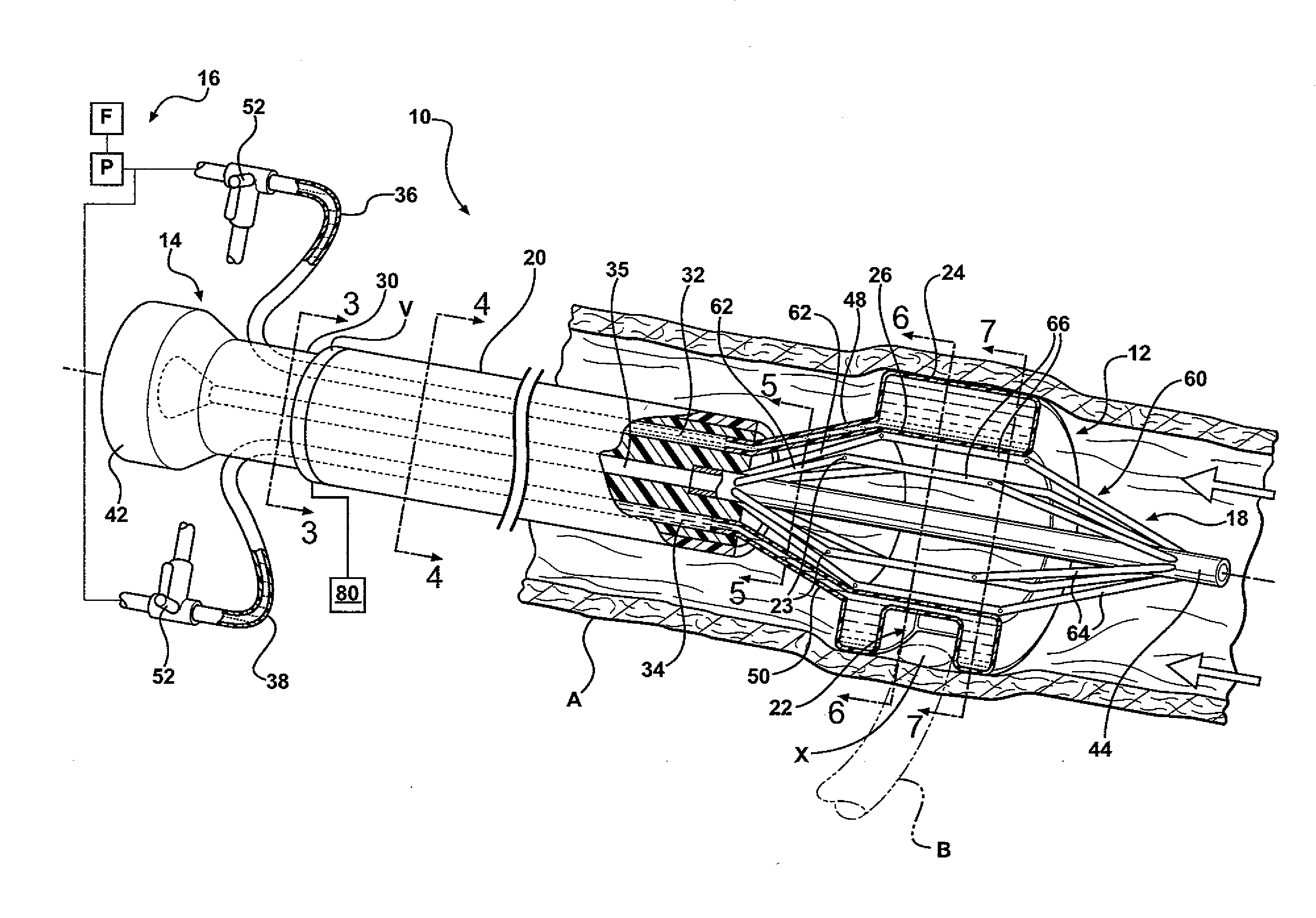
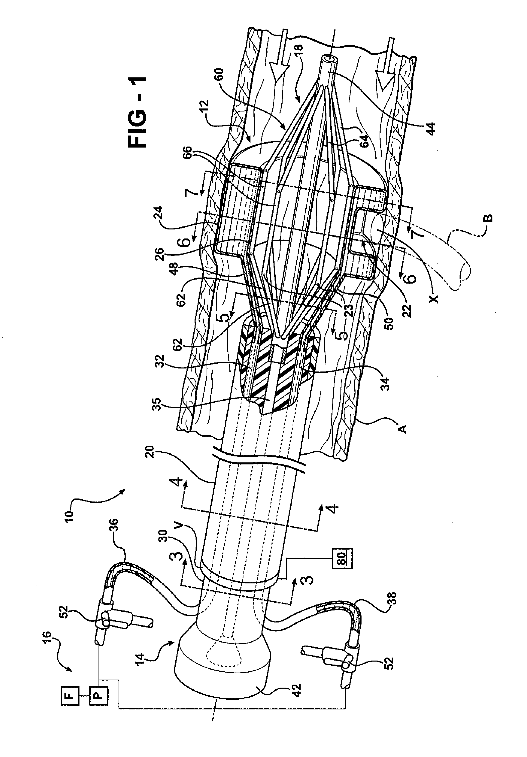
[0010]The present invention provides many advantages over the prior art. For instance, utilizing the strut assembly to support the occluding member provides the required occlusion of blood flow in the working space, while providing a large flow passage therethrough to allow blood flow to continue in the aorta during an anastomosis. More specifically, the strut assembly provides an open-framed support structure that invites blood flow therethrough while supporting the occluding member against the wall of the aorta.
[0011]The present invention allows more blood to flow beyond the target site, e.g., the anastomotic region, placing less “afterload” resistance on cardiac output, which will translate into greater utility in fragile patients. The volume of blood flow allowed through the flow passage defined by the expanded strut assembly is significantly greater than that allowed by prior designs.
[0012]Additionally, the methods of the present invention provide placement of the device through a remote femoral or brachial access, using percutaneous techniques or small incisions. The device replaces two occlusion clamps, allowing and facilitating minimally-invasive techniques. In addition, by avoiding the ischemia of aortic clamping, anastomoses of longer duration will be tolerable by patients. These longer durations will be necessary with laparoscopic suturing, or with the training of new surgeons.

Problems solved by technology

This interruption of aortic blood flow increases stress on the heart, potentially causing cardiac morbidity.
Such occlusion of blood flow inevitably leads to ischemia of downstream organs and extremities, which potentially leads to other complications.
Because the aorta itself is often diseased, with varying degrees of calcification within its wall, the act of placing occlusive clamps across the aorta risks injuring the aorta.
In addition, plaque within the wall is potentially liberated to embolize distally, which is undesirable.
However, these devices are designed to facilitate coronary artery bypass, and are not suited to other non-coronary applications.
These large incisions potentially lead to numerous complications, morbidity, or significant loss of body heat.

Method used


Image

  • Clampless anastomotic device
  • Clampless anastomotic device
  • Clampless anastomotic device

Examples


Embodiment Construction

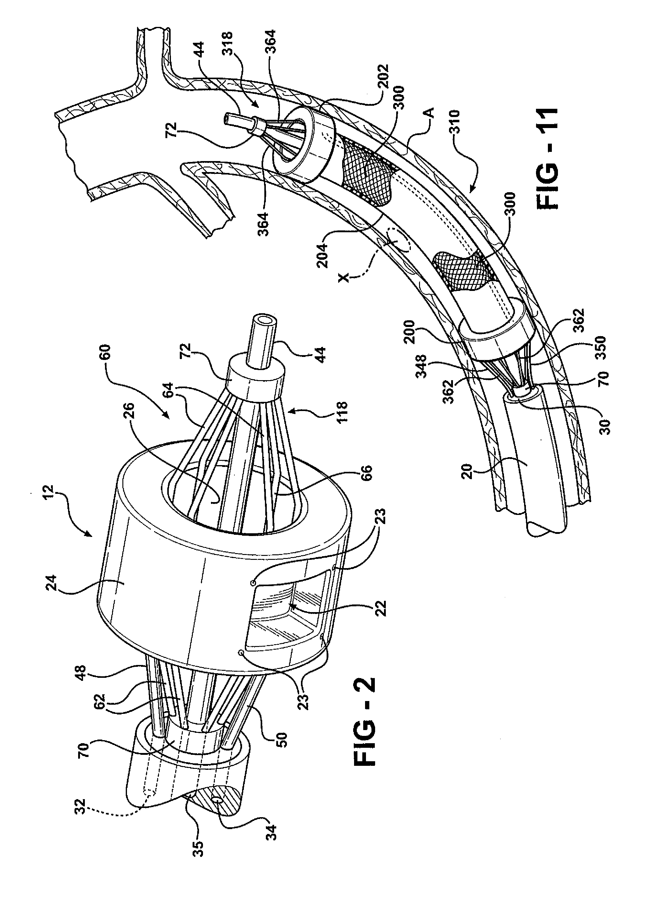
[0029]Referring to the Figures, wherein like numerals indicate like or corresponding parts throughout the several views, a device adapted for selectively occluding blood flow at a target site in a blood vessel while still maintaining blood flow through the blood vessel is generally shown at 10. The device 10 is particularly adapted for providing a working space in an aorta that is free of blood flow to perform an anastomosis, while still maintaining a significant amount of blood flow through the aorta. Arrows in FIG. 1 generally indicate blood flow. In FIG. 1, the device 10 is shown occluding blood flow from a target site X in a blood vessel, such as a thoracic or abdominal aorta A, to facilitate an end-to-side anastomosis of another blood vessel B to the aorta A. It should be appreciated that other uses of the device may be contemplated.

[0030]Referring to FIGS. 1-9, the device 10 comprises an occluding member 12, a catheter assembly 14 for endolumenal deployment of the occluding me...


PUM


Abstract

Described is a medical device and method for allowing fenestration of the aortic wall while maintaining distal perfusion and preventing external bleeding. The device isolates a segment of the aortic wall from the flowing column of blood using a balloon mounted on a metal alloy strut assembly. The strut assembly expands radially from a collapsed, low-profile configuration when uncovered by a constraining outer sheath. Aortic blood flow is allowed through the flow passage thus contained by the strut assembly within the center of the balloon. The balloon is inflated to contact the aortic wall. The balloon contains a pocket shaped to allow aortic fenestration. The balloon contains radiopaque markers to facilitate orientation and positioning of the pocket within the aorta. Other embodiments using spaced balloons are also disclosed.

Description

RELATED APPLICATIONS[0001]This application claims the benefit of U.S. Provisional Patent Application Ser. No. 60 / 910,838, filed on Apr. 10, 2007, the advantages and disclosure of which are hereby incorporated by reference in their entirety.FIELD OF THE INVENTION[0002]The present invention generally relates to a medical device used in vascular surgery and methods of use thereof. More specifically, the medical device is configured for endolumenal placement within a blood vessel, such as the thoracic or abdominal aorta, via remote arterial access. The medical device provides a working space in the blood vessel that is free of blood flow while still maintaining significant blood flow through the blood vessel. This is particularly useful in performing an aortic anastomosis.BACKGROUND OF THE INVENTION[0003]Various methods have been developed to revascularize diseased or occluded branches of the aorta. Direct reconstruction via bypass originating from the aorta proximally and anastomosed d...

Claims


Application Information

Patent Timeline
IPC IPC(8): A61M25/10A61M25/095A61M29/00A61F2/958
CPCA61B17/11A61B17/12045A61B17/12136A61B2017/1107A61B2017/1135A61B2017/12127
Inventor WILSON, DAVID B.
Owner WILSON DAVID B
Learn More