Press fit suture anchor and inserter assembly

a technology of suture anchor and inserter, which is applied in the field of suture anchors, can solve the problems of increasing the load and stress placed, joint injuries, and corresponding damage to the associated soft tissue, and achieves the effects of promoting natural bone growth, less susceptible to mechanical breakage, and easy penetration through the anchor

Inactive Publication Date: 2008-05-08
MUSCULOSKELETAL TRANSPLANT FOUND INC
View PDF10 Cites 92 Cited by
  • Summary
  • Abstract
  • Description
  • Claims
  • Application Information

AI Technical Summary

Benefits of technology

[0020]The present invention provides a technical advantage in that it provides a channel in the suture anchor in which a suture loop resides during insertion of the bone anchor into the bone while also allowing the driver to apply a driving force to the proximal end of the anchor so that the anchor is less susceptible to mechanical breakage.
[0021]Accordingly, one of the objects of the present invention is to provide an allograft suture anchor which promotes the use of natural bone growth in the bone bore hole.
[0023]It is another object of the present invention to provide a suture anchor in which the suture glides easily through the anchor to facilitate typing knots and sliding to knot to secure the tissue.
[0024]It is still another object of the present invention to provide a suture anchor which can be used with a wide variety of sutures from different manufacturers allowing the surgeon the choice of sutures and suture composition.
[0025]It is another object of the present invention to provide a suture anchor which is simple to apply and is mechanically stable when implanted in bone.
[0027]It is still another object of the present invention to provide a novel suture anchor for anchoring one end of a piece of conventional suture in bone which has high tissue acceptability, prevents back out and is reliable in use.

Problems solved by technology

These types of activities increase the loads and stress placed upon joints, sometimes resulting in joint injuries with corresponding damage to associated soft tissue.
This method is a time consuming procedure resulting in the generation of numerous bone tunnels.
The bone tunnels, which are open to various body fluids and infectious agents, may become infected, resulting in bone breakage and complications such as a longer bone-healing period may result.
A known complication of drilling tunnels across bone is that nerves and other soft tissue may be injured by the drill bit or orthopedic pin as it exits the far side of the bone.
Also, it may be anatomically impossible or at least very difficult to reach and / or secure a suture that has been passed through a tunnel.
When securing the suture or wire on the far side of the bone, nerves and soft tissues can also become entrapped and damaged.
Screws suffer from a disadvantage in that they tend to loosen with time, thereby requiring a second operation to remove the loosened screw.
In addition, when the screws are set in bone, the heads of the screws frequently protrude above the surface of the bone in which they are set, thereby presenting an abrasive surface which may create wear problems with surrounding tissue.
Once a hole has been made in the bone it may be impossible to relocate the hole a small distance away from its original position due to the disruption of the bone structure created by the initial hole.
Staples have also been known to crack the bone during deployment, or to accidentally transect the object (e.g. soft tissue) being attached to the bone, since it tends to be difficult to precisely control the extent of the staple's penetration into the bone.
Additionally, once the staple has been set into the bone, the position of the staple is then effectively determined, thereby making it impossible to thereafter adjust the position of the staple or to adjust the degree of tension being applied to the object which is being attached to the bone without removing the staple and setting a new staple.
Although most suture anchors described in the art are made from non-absorbable materials, the use of absorbable suture anchors may result in fewer complications since the suture anchor is absorbed and replaced by bone over time.
Another problem in the prior art is that the suture does not glide easily through the anchor making typin knots and sliding the knot to secure the tissue difficult.
It is also a problem that most of the bone anchors currently used are prepacked with sutures attached in kit form forcing the surgeon to use a specific type of suture and the hospital to carry large numbers of bone anchors in inventory with varying suture sizes.

Method used


Image

  • Press fit suture anchor and inserter assembly
  • Press fit suture anchor and inserter assembly
  • Press fit suture anchor and inserter assembly

Examples


Embodiment Construction

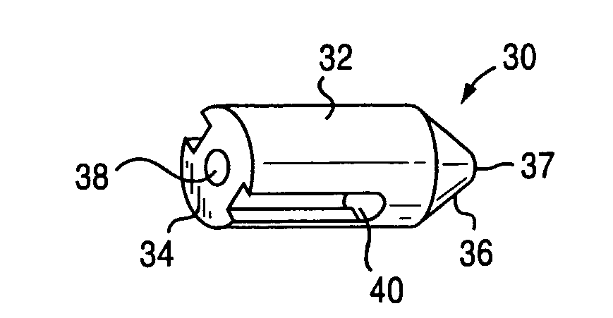
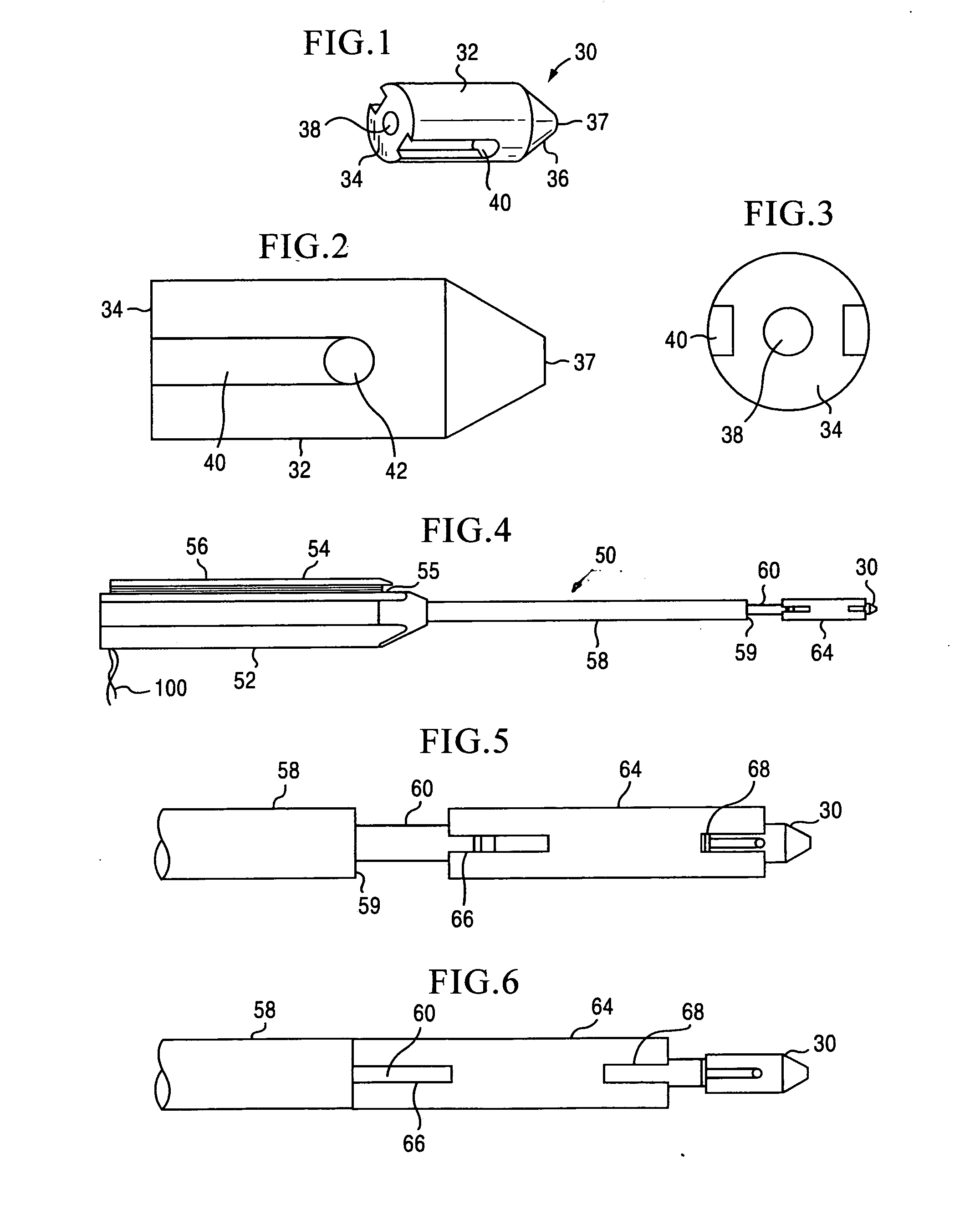
[0053]The preferred embodiment and the best mode of the invention as shown in FIGS. 1 through 24 shows a suture anchor 30 with a cylindrical body 32 having a flat proximal end 34 and a truncated conical distal portion 36 having a flat end surface 37 which is initially inserted into a bore 206 cut in the bone mass as shown in FIGS. 19-24. The flat proximal end 34 defines a centrally located blind bore 38 which is sized to receive the end 62 of an inserter device 50. The conical distal end 37 tapers inward in about from 30° to 45° from the sides of the cylindrical body toward the center longitudinal axis of the suture anchor for self centering insertion into bone bore 206. Side grooves 40 are cut in the exterior surface of the cylindrical body and run from about 50% to about 75% of the length of the cylindrical body 32 where they intersect a transverse throughgoing bore 42 in the cylindrical body 32 and together form a seat in the suture anchor for the suture strand or strands 100 whi...


PUM


Abstract

A sterile suture anchor and insertion kit with the suture anchor having a cylindrical body portion with a generally tapered distal end portion and flat end. A plurality of parallel longitudinal grooves are cut into the cylindrical body and a connecting throughgoing bore is cut through the cylindrical body engaging the plurality of longitudinal grooves. An inserter driver is adapted to be mounted to the suture anchor, the driver comprising a handle with a drive shaft mounted to the handle, and a slidable sleeve mounted on the drive shaft which holds the suture anchor. A guide member comprising a handle with a hollow sleeve extending therefrom is used to hold a punch against the area on which a blind bore is formed to form the blind bore after which the inserter driver is mounted in the guide member sleeve to guide the slidable sleeve of the inserter driver and associated suture anchor into the blind bore.

Description

RELATED APPLICATIONS[0001]This are no related applications.STATEMENT REGARDING FEDERALLY SPONSORED RESEARCH OR DEVELOPMENT[0002]Not applicable.REFERENCE TO SEQUENCE LISTING, A TABLE OR A COMPUTER PROGRAM LISTING COMPACT DISC APPENDIX[0003]None.BACKGROUND OF THE INVENTION[0004]1. Field of Invention[0005]The field of art to which this invention relates is generally directed to suture anchors and more specifically to a press fit suture anchor constructed of allograft bone which holds a suture and a punch and inserter device for inserting the suture anchor.[0006]2. Description of the Prior Art[0007]As the treatment of injuries to joints and soft tissue has progressed, a need has developed for medical devices which can be used to attach tendons, ligaments and other soft tissue to bone. When surgically repairing an injured joint, it is preferable to restore the joint by reattaching the damaged soft tissues such as ligaments and tendons to a bone rather than replacing them with an artifici...

Claims


Application Information

Patent Timeline
Patent Type & Authority Applications(United States)
IPC IPC(8): A61B17/04
CPCA61B17/0401A61B17/1714A61B17/92A61B2017/0438A61B2017/0412A61B2017/0414A61B2017/0409
Inventor STEINER, ANTON J.KNIGHT, DAVID I.CHAVISTA PARA, CESAR D.SHOCK, JAMES
Owner MUSCULOSKELETAL TRANSPLANT FOUND INC
Why Eureka
Try Eureka