Threaded suture anchor and inserter device

a technology of threaded sutures and anchors, which is applied in the field of threaded sutures, can solve the problems of numerous bone tunnels, nerves and other soft tissue may be injured by drill bits or orthopaedic pins, and joint injuries with corresponding damage to associated soft tissue, so as to promote the use of natural bone growth, prevent back pain, and high tissue acceptability

Inactive Publication Date: 2008-05-08
MUSCULOSKELETAL TRANSPLANT FOUND INC
View PDF21 Cites 82 Cited by
  • Summary
  • Abstract
  • Description
  • Claims
  • Application Information

AI Technical Summary

Benefits of technology

[0020]The present invention provides a technical advantage in that it provides a channel in the suture anchor in which a suture loop resides during insertion of the bone anchor into the bone while also allowing the driver to apply torque along the sides of the bone anchor so that the anchor is less susceptible to mechanical breakage.
[0021]It is thus an object of the present invention to provide a suture anchor which can be used with a wide variety of sutures from different manufacturers allowing the surgeon the choice of sutures and suture composition, thus saving the hospital from stocking a large number of prepacked bone anchors and suture kits.
[0022]Therefore, it is another object of the present invention to provide a suture anchor which is simple to apply and is mechanically stable when implanted in bone.
[0024]Accordingly, one of the objects of the present invention is to provide an allograft suture anchor which promotes the use of natural bone growth in the bone bore hole.
[0026]And another object of the present invention is to provide a novel suture anchor for anchoring one end of a piece of conventional suture in bone which has high tissue acceptability, prevents back out and is reliable in use.

Problems solved by technology

These types of activities increase the loads and stress placed uponjoints, sometimes resulting injoint injuries with corresponding damage to associated soft tissue.
This method is a time consuming procedure resulting in the generation of numerous bone tunnels.
A known complication of drilling tunnels across bone is that nerves and other soft tissue may be injured by the drill bit or orthopaedic pin as it exits the far side of the bone.
Also, it may be anatomically challenging to reach and / or secure a suture that has been passed through a tunnel.
When securing the suture or wire on the far side of the bone, nerves and soft tissues can become impinged and damaged.
Screws suffer from a disadvantage in that they may loosen with time, thereby requiring a second operation to remove the loosened screw.
In addition, when the screws are set in bone, the heads of the screws frequently protrude above the surface of the bone in which they are set, thereby presenting an abrasive surface which may create wear problems with surrounding tissue.
Once a hole has been made in the bone it may be impossible to relocate the hole at a small distance away from its original position due to the disruption of the bone structure created by the initial hole.
Although most suture anchors described in the art are made from non-absorbable materials, the use of absorbable suture anchors may result in fewer complications since the suture anchor is absorbed and replaced by bone over time.
It is also a problem that most of the bone anchors currently used are prepacked with sutures attached in kit form forcing the surgeon to use a specific type of suture and the hospital to carry large numbers of bone anchors in inventory with varying suture sizes.

Method used


Image

  • Threaded suture anchor and inserter device
  • Threaded suture anchor and inserter device
  • Threaded suture anchor and inserter device

Examples


Embodiment Construction

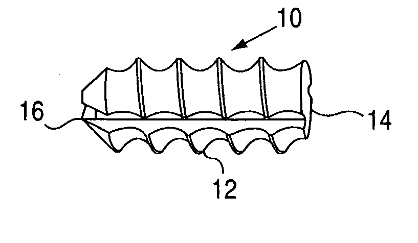
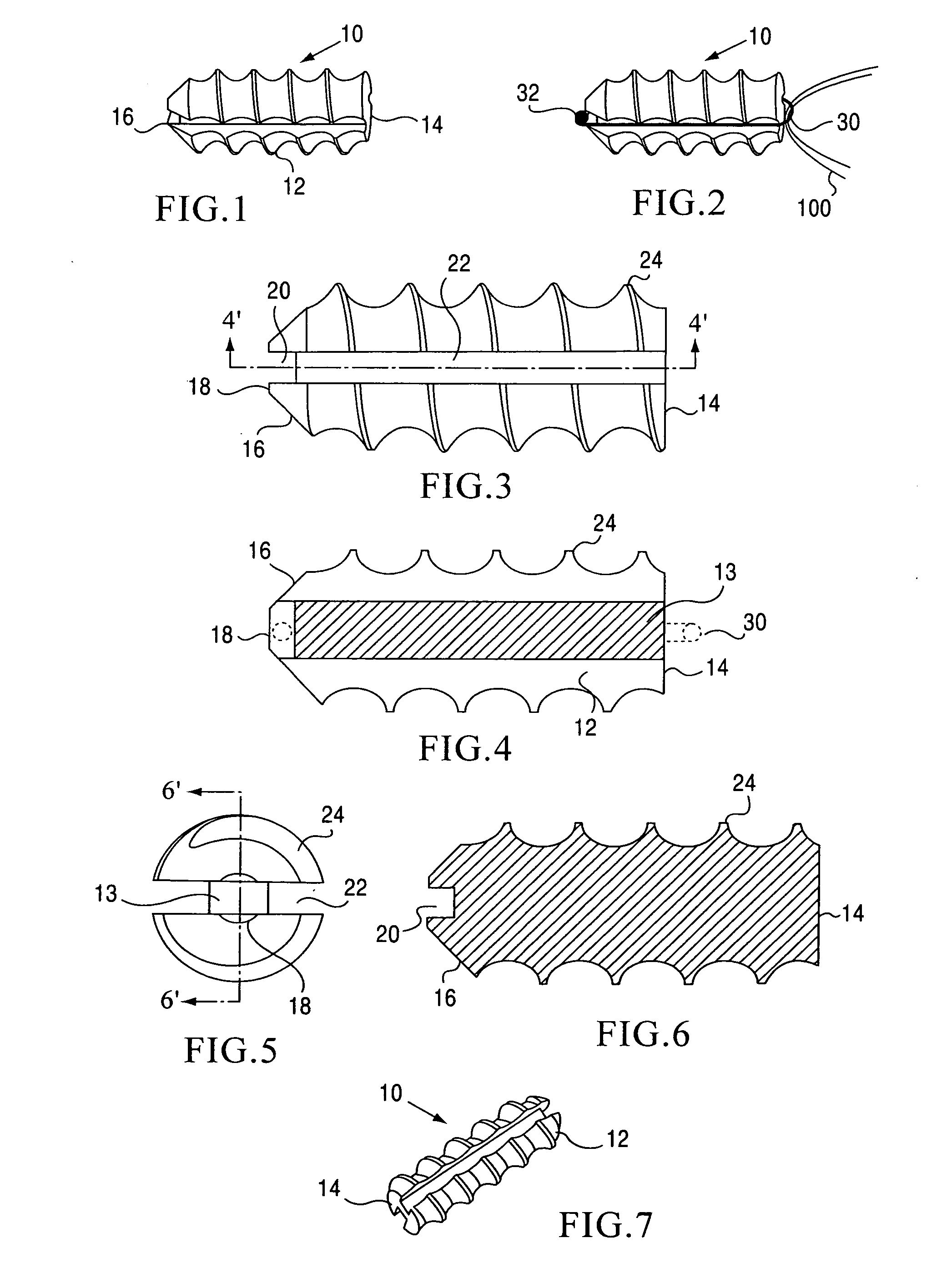
[0039]The preferred embodiment and the best mode of the invention as shown in FIGS. 1 through 11 is a suture anchor 10 with a cylindrical body 12 having a flat proximal end 14 and a tapered distal end 16 with a planar transverse tip 18 which is initially inserted into a bore cut in the bone mass (not shown). The distal end 16 tapers inward in about 45° from the center longitudinal axis of the suture anchor for self centering insertion and has a smooth flat end surface defining a connecting groove 20 which connects side grooves 22 and forms a seat for the suture loop 30. A helical thread 24 is cut in the cylindrical body 12. Preferably, the bone anchor is manufactured from human bone which is formed of mineralized cortical bone. Alternatively, the anchor body may be partially demineralized and alternately treated with bone morphogenic protein, hylauronic acid and a phosphate buffer for quicker bone formation.

[0040]It is also envisioned that the suture anchor may be manufactured from ...


PUM


Abstract

A sterile suture anchor and drive kit with the suture anchor having a cylindrical body portion with a generally tapered distal end portion and a screw thread extending along a cylindrical body portion. A plurality of parallel longitudinal grooves are cut into the cylindrical body interrupting opposed portions of the screw thread and a connecting groove is cut through the distal end portion of the suture anchor engaging the plurality of longitudinal grooves. A closed suture loop is mounted in the longitudinal grooves and the connecting groove. A driver is adapted to be mounted to the suture anchor, the driver comprising a handle with a tube mounted to the handle, the tube being provided with outwardly extending drive tip members adapted to be inserted into the suture anchor longitudinal grooves to engage the groove side walls of the suture anchor to apply driving torque to the suture anchor.

Description

RELATED APPLICATIONS[0001]This are no related applications.STATEMENT REGARDING FEDERALLY SPONSORED RESEARCH OR DEVELOPMENT[0002]Not applicable.REFERENCE TO SEQUENCE LISTING. A TABLE OR A COMPUTER PROGRAM LISTING COMPACT DISC APPENDIX[0003]None.BACKGROUND OF THE INVENTION[0004]1. Field of Invention[0005]The field of art to which this invention relates is generally directed to suture anchors and more specifically to threaded suture anchors constructed of allograft bone which hold a suture.[0006]2. Description of the Prior Art[0007]As the treatment of injuries to joints and soft tissue has progressed, a need has developed for medical devices which can be used to attach tendons, ligaments and other soft tissue to bone. When surgically repairing an injured joint, it is preferable to restore the joint by reattaching the damaged soft tissues such as ligaments and tendons to bone rather than replacing them with an artificial material.[0008]An increase in the incidence of injuries to joints ...

Claims


Application Information

Patent Timeline
Patent Type & Authority Applications(United States)
IPC IPC(8): A61B17/04
CPCA61B17/0401A61B2017/0409A61B2017/0414A61B2017/0619A61B2017/0445A61B2017/0458A61B2017/044
Inventor STEINER, ANTON J.KNIGHT, DAVID I.CHAVISTA PARA, CESAR D.SHOCK, JAMES
Owner MUSCULOSKELETAL TRANSPLANT FOUND INC
Why Eureka
Try Eureka