
Multiblade knife unit

a multi-blade knife and blade technology, applied in the direction of thrusting weapons, white arms/cold weapons, weapons, etc., can solve the problems of significant use injury risk of opposite projecting cutting edges, parallel cutting edges which are not normally useful, etc., to facilitate quick and easy removal and replacement of slide-out blades

Inactive Publication Date: 2008-05-15
I D L TECH TOOLS
View PDF26 Cites 29 Cited by
  • Summary
  • Abstract
  • Description
  • Claims
  • Application Information

AI Technical Summary

Benefits of technology

[0006]The pivotally mounted knife blade, in the preferred form, includes a short stub post positioned in spaced relation to the pivotally mounted end thereof, for fingertip engagement to facilitate knife blade displacement from the normally stored to the deployed position. A spring plate mounted within the handle housing shifts laterally in a first direction when the pivoting knife blade is in the deployed position to engage and lock with a matingly shaped base end of the knife blade, thereby precluding unintended return movement from the deployed position to the stored position. An edge of this spring plate is exposed and configured for fingertip engagement to shift the spring plate in a second direction, thereby releasing the knife blade and permitting pivotal return thereof to the stored position.
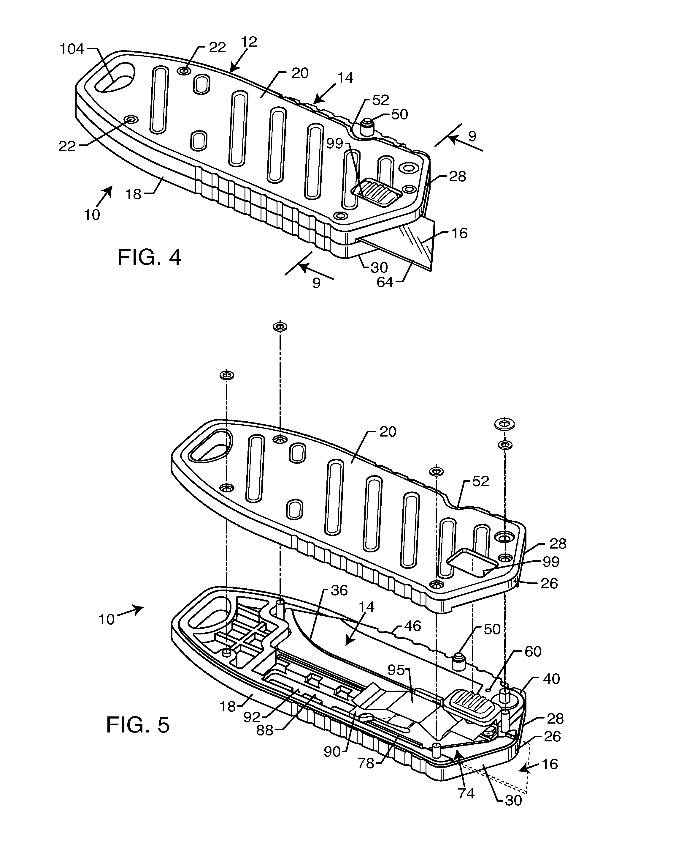
[0008]A release button on the handle housing is depressed for releasing the utility knife blade from the slide clip, thereby facilitating quick and easy slide-out blade removal and replacement. The release button is carried at one end of a spring tab mounted within the handle housing, with said release button being externally exposed through a button port formed in the handle housing. When the slide clip is shifted to the advanced position, the release button can be depressed to retract the mounting key on the slide clip from the mounting recess on the utility blade, thereby releasing the utility blade for manual grasping and slide-out separation from the slide clip and handle housing. Accordingly, a replacement utility blade with a sharp cutting edge can be slidably installed on the slide clip, followed by spring-retraction of the release button for re-engagement of the slide clip mounting key with the blade mounting recess.

Problems solved by technology

By contrast, while multiple blades can be deployed simultaneously, the blades typically define parallel cutting edges which are not normally useful in this configuration for performing different types of cutting tasks.
Once again, while it is possible to deploy both types of knife blades at the same time, the oppositely projecting cutting edges pose a significant risk of use injury.

Method used


Image

  • Multiblade knife unit
  • Multiblade knife unit
  • Multiblade knife unit

Examples


Embodiment Construction

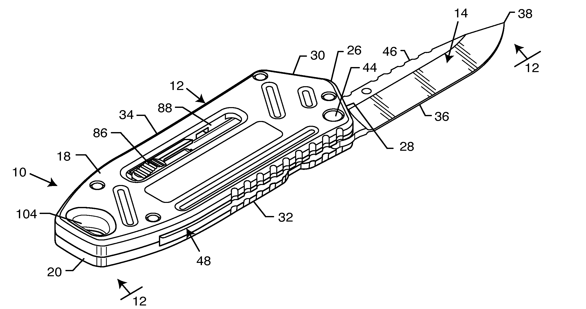
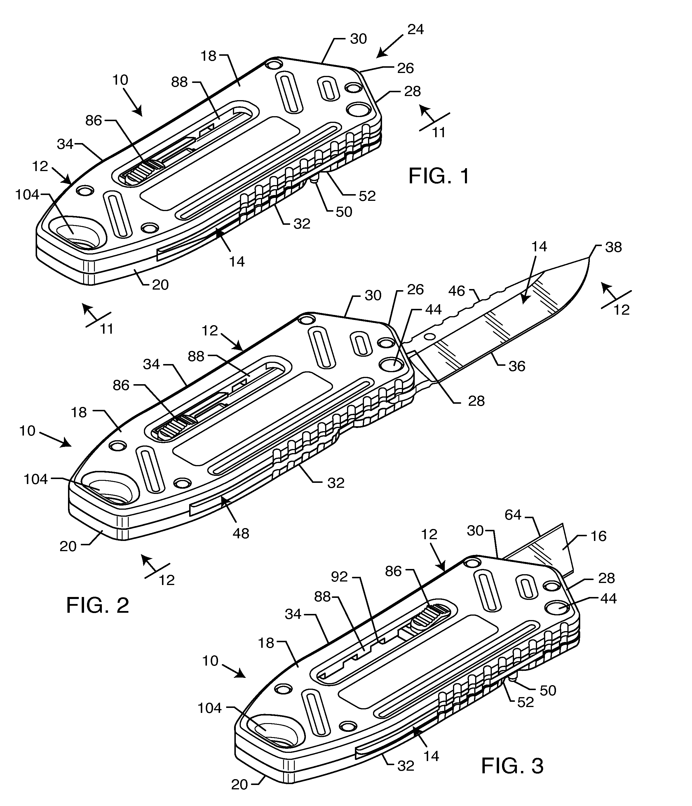
[0026]As shown in the exemplary drawings, a multiblade knife unit referred to generally in FIGS. 1-4 by the reference numeral 10 comprises a handle housing 12 carrying a plurality of knife blades of different types, wherein the multiple knife blades are adapted for movement between a normal stored position and a deployed position projecting outwardly from a common end of the handle housing 12. The exemplary drawings show the multiple knife blades in the form of a pivoting knife blade 14 (FIG. 2) and a slidably mounted razor-type utility blade 16 (FIGS. 3-4). Both blades 14, 16 can be deployed at the same time, if desired.

[0027]The multiblade knife unit 10 of the present invention generally comprises the handle housing 12 having a relatively compact and preferably externally textured or grooved geometry for facilitated manual grasping and holding during use. As shown, the handle housing 12 comprises an upper housing member 18 having a size and shape for mated fit with a lower housing...


PUM


Abstract

A multiblade knife unit includes knife blades of different type normally stored within and adapted for deployment from a common end of a handle housing. A pivoting knife blade is supported for pivotal movement between a stored position nested substantially within one side edge of the handle housing, and a deployed position projecting from one end of the handle housing. A razor-type utility knife blade is supported by a slide clip for sliding displacement between a retracted position stored and concealed within the handle housing, and an advanced position projecting from said one end of the handle housing. A release button on the handle housing is depressed for releasing the utility knife blade from the slide clip for facilitating quick and easy slide-out blade removal and replacement. In one form, the knife unit may further include driver bits interchangeably mounted at an opposite end of the handle housing.

Description

BACKGROUND OF THE INVENTION[0001]This invention relates generally to an improved multiblade knife unit including a plurality of knife blades of different type normally stored within and adapted for deployment from a handle housing. More particularly, this invention relates to an improved multiblade knife unit wherein multiple knife blades such as a pivotally mounted knife blade and a slidably mounted utility blade are deployable from a common end of the handle housing.[0002]Multiblade knife units are generally known in the art, wherein a plurality of knife blades are carried by a common knife handle. In such knife units, the handle comprises a housing structure adapted for movably supporting each of the multiple knife blades for individual displacement between a normal stored position nested at least partially within the handle housing, and a deployed position with a blade cutting edge exposed for use. In this regard, conventional so-called pocket knives are known wherein multiple p...

Claims


Application Information

Patent Timeline
IPC IPC(8): B26B3/06
CPCB26B1/02B26B5/00B26B1/08B26B1/044
Inventor SEBER, BRETT P.CARMICHAEL, ERIC B.TOM, WESLEY JAMES
Owner I D L TECH TOOLS
Learn More