Turbofan emergency generator

a generator and engine technology, applied in the direction of machines/engines, mechanical equipment, magnetic circuit shapes/forms/construction, etc., can solve the problems of inability to retract in flight, significant challenges in aircraft design, containment issues, etc., and achieve the effect of increasing the speed of the generator

Active Publication Date: 2008-05-15
PRATT & WHITNEY CANADA CORP +1
View PDF21 Cites 26 Cited by
  • Summary
  • Abstract
  • Description
  • Claims
  • Application Information

AI Technical Summary

Benefits of technology

[0007]A turbine engine emergency power system includes low and high pressure spools, the lower pressure spool including a low pressure compressor. A turbofan is coupled to the low pressure spool. The turbofan drives the low pressure spool in a windmill condition in which the low pressure turbine fails to provide rotational drive to the turbofan. A generator is rotationally

Problems solved by technology

Finding a suitable location for the RAT and designing a deployment system to position the RAT into the airstream can present significant challenges for the aircraft design.
An additional consideration is that, there is a possibility that the unshrouded RAT blades could separate from their hub at high velocity during RAT operation, presenting a containment issue.
Also, to minimize installation envelope, RAT systems are typically designed such that once that RAT is deployed it cannot be retracted in flight.
Again, un

Method used


Image

  • Turbofan emergency generator
  • Turbofan emergency generator
  • Turbofan emergency generator

Examples


Embodiment Construction

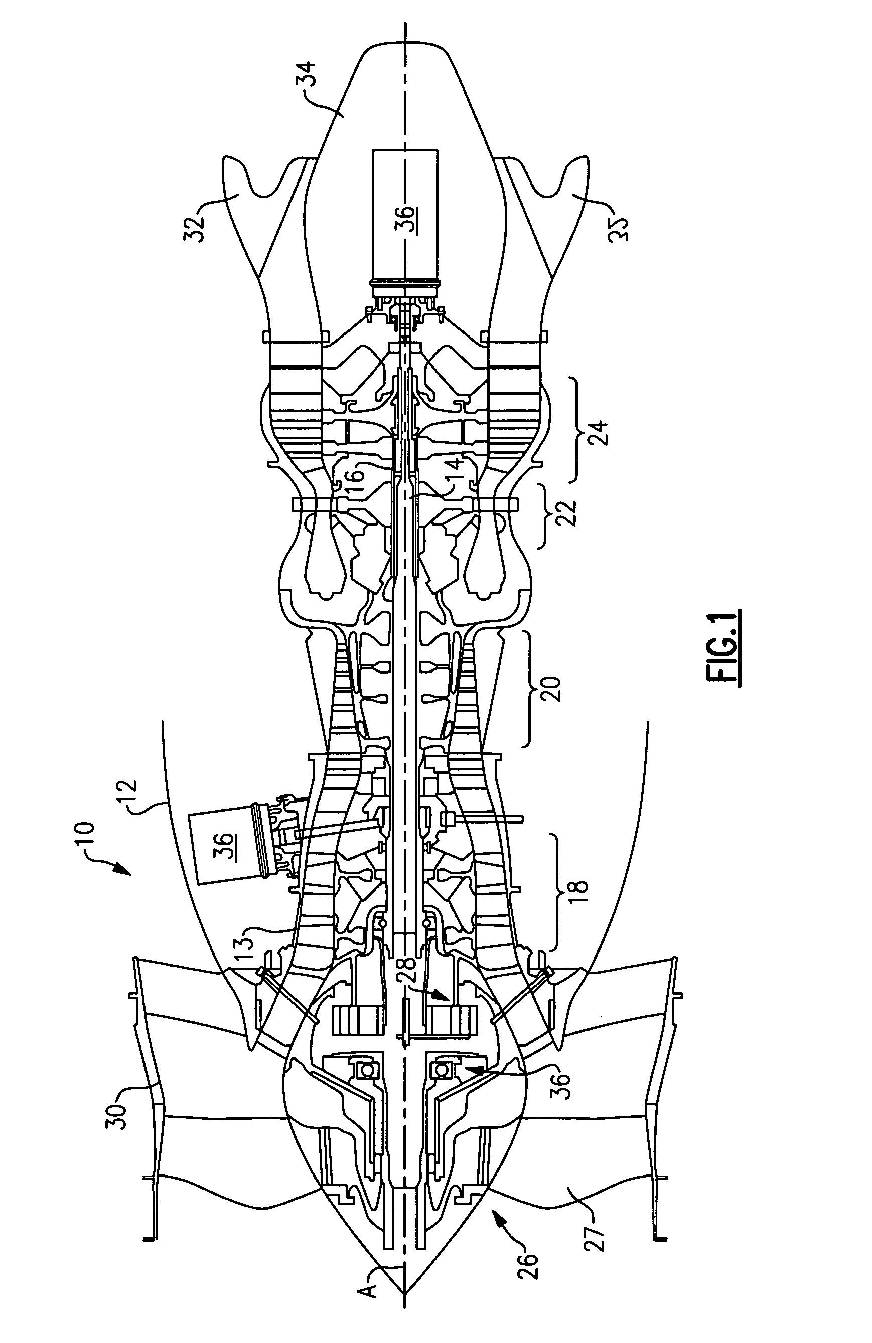
[0013]An example turbine engine 10 is shown in FIG. 1. The turbine engine 10 includes a core 12 having a housing 13. The example turbine engine 10 includes a two spool arrangement provided by first and second shafts 14, 16 that rotates about a common axis A. The first shaft 14 corresponds to a low pressure spool, and the second shaft 16 corresponds to a high pressure spool. The shafts 14, 16 rotate about an axis A. The first shaft 14 is coupled to a low pressure compressor section 18 and a low pressure turbine section 24. The second shaft 16 is coupled to a high pressure compressor section 20 and a high pressure turbine section 22. The shafts 14, 16 are supported within the housing 13 for rotation and typically include multiple portions secured to one another, as is known in the art.

[0014]A turbofan 26 having multiple blades 27 is typically coupled to the first shaft 14 by an epicyclic gear train 28, which reduces the speed of the turbofan 26. The turbofan 26 is arranged within a na...


PUM


Abstract

A turbine engine emergency power system includes low and high pressure spools, the lower pressure spool including a low pressure compressor. A turbofan is coupled to the low pressure spool. The turbofan drives the low pressure spool in a windmill condition in which the low pressure turbine fails to provide rotational drive to the turbofan. A generator is rotationally driven by the low pressure spool in the windmill condition. A gear train is used to increase the speed of the generator in one example. In one example embodiment, a centrifugal clutch is used to selectively decouple the generator from the low pressure spool at a predetermined engine speed, which corresponds to normal operating speeds when the turbine engine is under power.

Description

BACKGROUND OF THE INVENTION[0001]This invention relates to a turbofan driven emergency generator, which is driven by the turbofan when the turbine engine loses power.[0002]In modern, turbofan power aircraft, an emergency power source is required for control of flight surfaces in the event of the total loss of the availability of the primary power sources; i.e. engine driven hydraulic pumps and / or engine driven electrical generators. For small airplanes, this power is provided by the energy stored in aircraft batteries. For larger airplanes, a single ram air turbine (RAT) with an integral generator or hydraulic pump is provided for deployment in an emergency situation only. Here, the emergency power source is the aircraft's own airspeed (kinetic energy) and altitude (potential energy).[0003]To derive maximum power from the ram air, a RAT must be located away from aircraft surfaces that would disturb the smooth (laminar) entry of air into the RAT blades. In practice, this usually mean...

Claims


Application Information

Patent Timeline
IPC IPC(8): F02C3/00F02C7/00
CPCF02C7/262F05D2220/34F02C7/32
Inventor WELCH, RICHARD C.BUECHE, GERARD H.DEGROFF, WILLIAM T.ALBERO, JOSEMAKUSZEWSKI, JERZY
Owner PRATT & WHITNEY CANADA CORP
Why Eureka
Try Eureka