Fluid pressure sensing method and apparatus

a technology of fluid pressure and sensing method, applied in the direction of fluid pressure measurement by mechanical elements, instruments, measurement devices, etc., can solve the problem of time-consuming

Active Publication Date: 2008-05-15
BENDIX COMML VEHICLE SYST LLC
View PDF99 Cites 19 Cited by
  • Summary
  • Abstract
  • Description
  • Claims
  • Application Information

AI Technical Summary

Benefits of technology

[0044]The holding provisions may further include a flat member having an opening permitting access to a surface of the switch actuator the flat member being fastened to the body such that the resilient switch actuator provides a seal to prevent ingress and egress of fluid relative to the cavity through the switch actuator opening.
[0045]In accordance with another aspect of the invention, there is provided a pressure sensor apparatus. The pressure sensor apparatus includes a circuit carrier apparatus including a substrate having first and second opposite edges, first and second opposite ends and first and second opposite facing surfaces. The apparatus also includes a circuit portion on the first end and an antenna portion on the second end. The antenna portion includes a radio frequency antenna and the circuit portion includes at least one power supply located at a side of the substrate and such that the power supply projects outwardly from the substrate. The circuit portion also includes a pressure sensor having a flat surface and a pressure sensor opening on the flat surface, the flat surface being generally parallel and spaced apart from the first opposite facing surface and adjacent the power supply. The circuit portion further includes a transmitter connected to the pressure sensor for producing a signal for radiation by the antenna in response to a sense signal produced by the pressure sensor. The pressure sensor apparatus includes a housing for housing the circuit carrier apparatus. The housing includes a body that has an outer wall defining a cavity operably configured to hold the circuit portion of the substrate. The body also has an inner wall inside the cavity defining a pressure sensing chamber, an opening in the inner wall, a seal about the opening and aligning provisions for aligning the pressure sensor opening with the opening in the inner wall to provide for communication of fluid between the pressure sensing chamber and the pressure sensor opening. The body further has urging provisions for urging the pressure sensor against the seal, such that the opening in the pressure sensor is in fluid communication with the opening in the pressure sensing chamber and such that the seal prevents ambient pressure from interfering with communication of fluid between the opening in the pressure sensor and the opening in the pressure sensing chamber. The housing also includes potting material in the cavity and about the circuit portion for securing the substrate in the cavity. The housing further includes a cover for covering the antenna portion, the cover being sealingly engaged with the housing to prevent ingress and egress of fluid relative to the cavity.

Problems solved by technology

A problem with the above type of sensor is that it must be removed to allow access to the valve in the valve stem in order to change the air pressure in the tire.
This can be time consuming, especially where there are individual sensors on each wheel of a large. transport truck for example.

Method used


Image

  • Fluid pressure sensing method and apparatus
  • Fluid pressure sensing method and apparatus
  • Fluid pressure sensing method and apparatus

Examples


Embodiment Construction

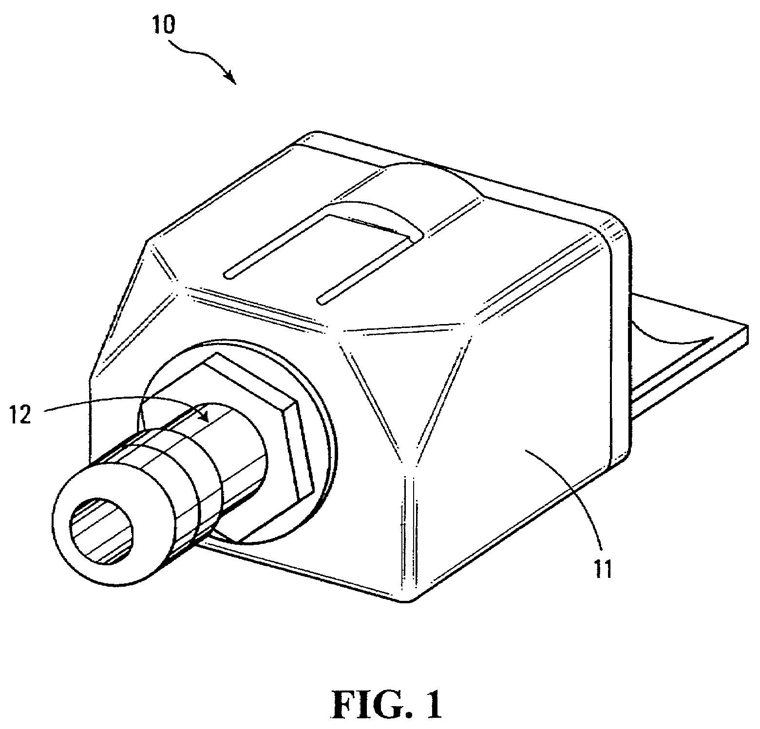
[0075]Referring to FIG. 1, a pressure sensing system according to a first embodiment of the invention is shown generally at 10 and includes a pressure sensor apparatus 11 mounted on a pressure coupler shown generally at 12.

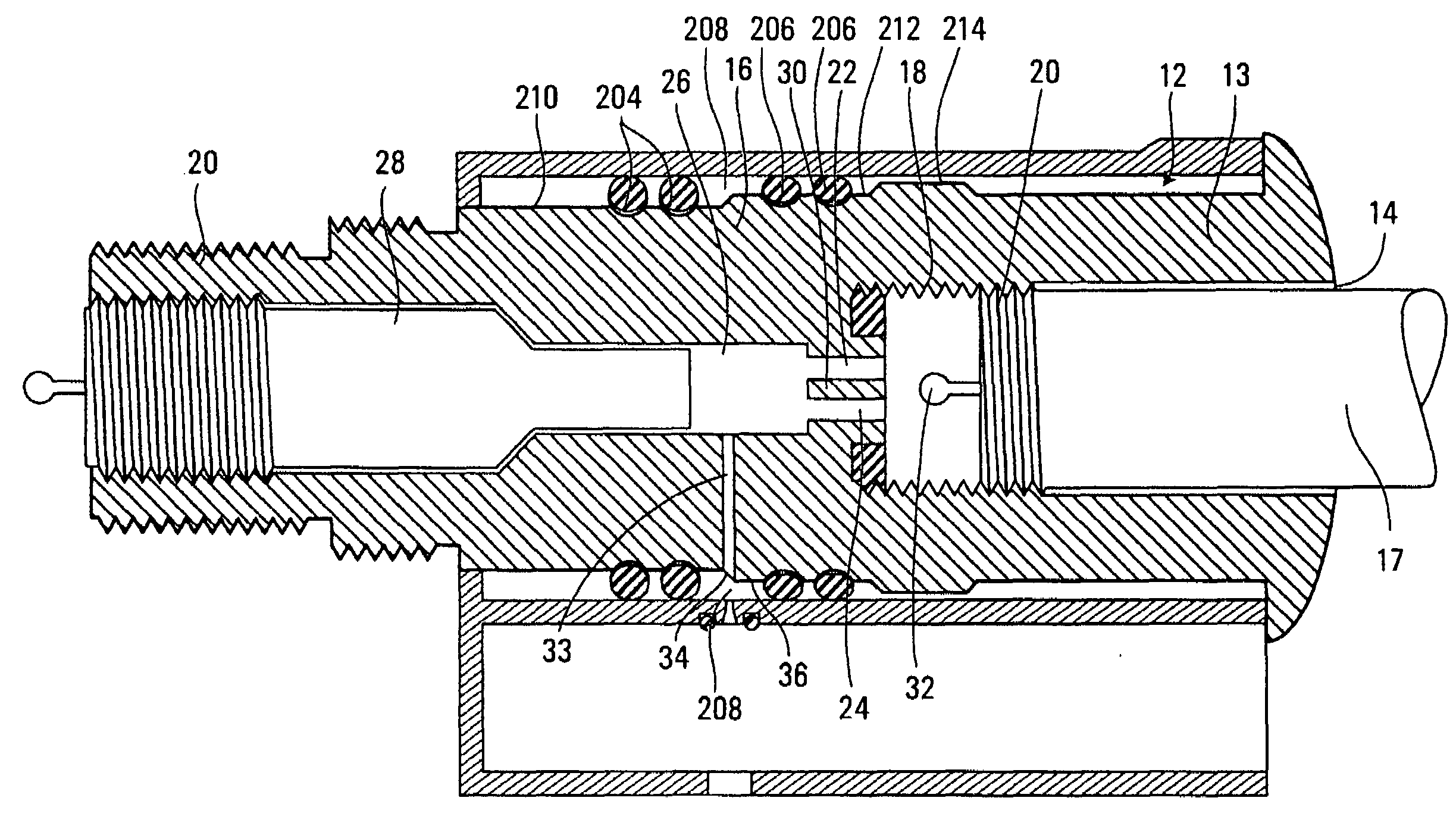
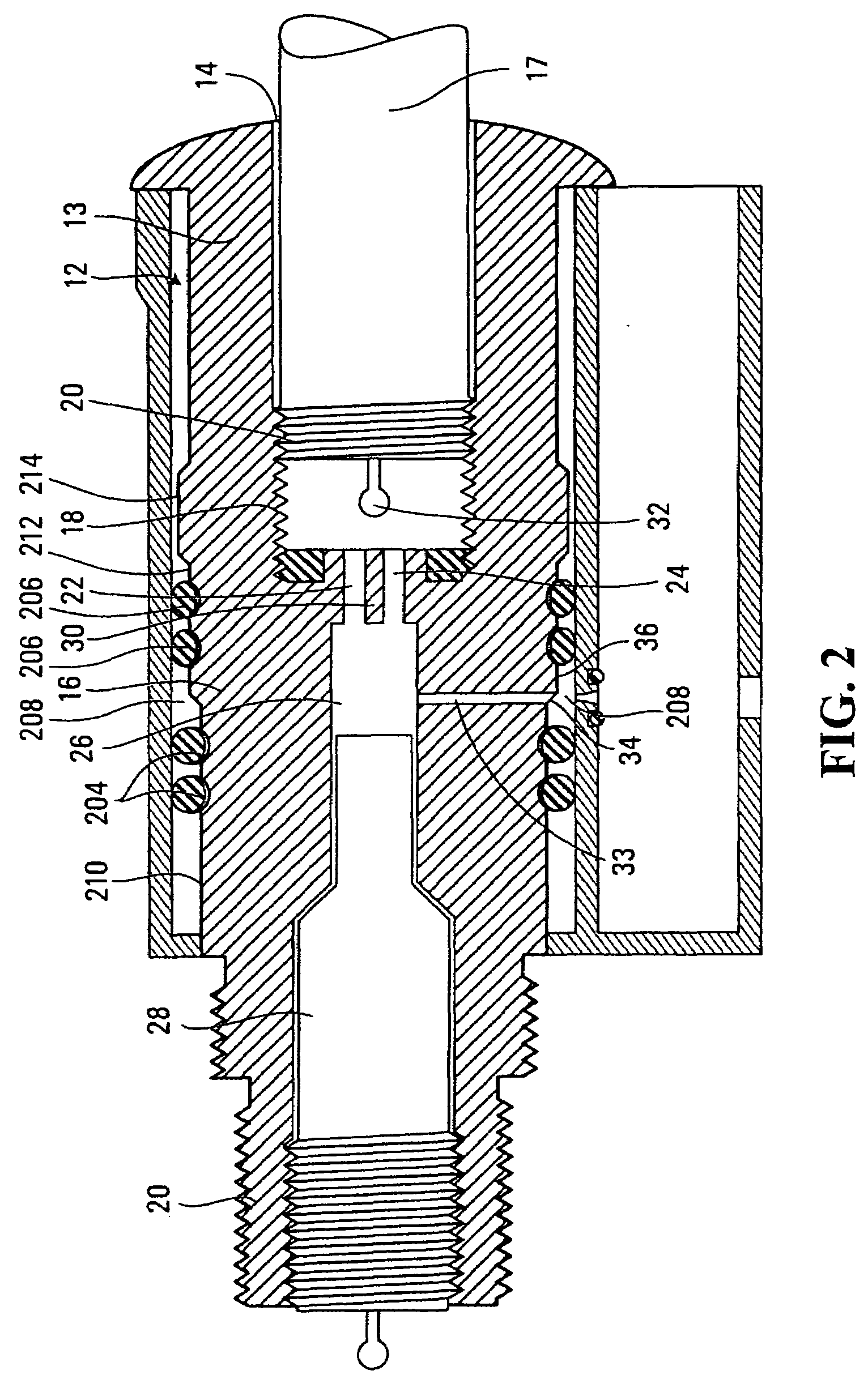
[0076]Referring to FIG. 2, the pressure coupler 12 in this embodiment includes a body 13 having an inlet opening 14 for receiving pressurized fluid from a pressurized system. In one embodiment, the pressurized system may include a tire (not shown) having a valve stem 17 operable to be received in the inlet opening 14. In such an embodiment, the inlet opening 14 may be threaded as shown at 18, for example, to receive corresponding threads 20 of an end of the valve stem 17.

[0077]In this embodiment, the body 13 also has a projection 16 having first and second passages 22 and 24 in communication with the inlet opening 14 which are connected to and in communication with a valve bore 26 operable to receive a valve core 28 in sealing engagement therein.

[0078]Adjacent the...


PUM

PropertyMeasurementUnit
pressureaaaaaaaaaa
conductoraaaaaaaaaa
movementaaaaaaaaaa

Abstract

A method and apparatus for producing a circuit carrier for mounting components of a pressure sensing circuit, circuit carrier formed thereby, an apparatus for housing a pressure sensor circuit carrier to form a pressure sensing apparatus and a pressure sensing system using the pressure sensing apparatus and a coupler for coupling the pressure sensing apparatus to a pressurized system. A housing has provisions for aligning and urging a circuit carrier to sealingly position a pressure sensor adjacent an opening in a wall extending through of housing. The wall defines a pressure sensing chamber operable to cooperate with a pressure coupler having a profile that sealingly engages the wall.

Description

BACKGROUND OF THE INVENTION[0001]1. Field of Invention[0002]This invention relates to a fluid pressure sensing method and apparatus and components thereof.[0003]2. Description of Related Art[0004]Pressure sensors for pressurized systems are known. Some pressure sensors are designed for permanent installation on a pressurized system and may have a pipe coupling or hose coupling to facilitate connection to the system. Often, screw threads are involved on such couplings and threaded engagement with the coupling secures the pressure sensor thereto.[0005]One example of an area where such sensors are used is in vehicle tire pressure monitoring. Typically, pressure sensors for tire pressure monitoring are formed with housings that have a cylindrical protrusion having an inside threaded wall for engagement with an outside threaded portion of a valve stem on a tire. Typically, the tire is filled with air and then the pressure sensor is screwed on to the valve stem in such a manner that it co...

Claims


Application Information

Patent Timeline
Patent Type & Authority Applications(United States)
IPC IPC(8): G01L7/00
CPCB60C23/0408G01L19/086B60C23/0496
Inventor SHEIKH-BAHAIE, KIANLAMMERS, SHAWNPATTERSON, ROBERT GORDON
Owner BENDIX COMML VEHICLE SYST LLC
Why Eureka
Try Eureka