Impact filter with grease trap

Active Publication Date: 2008-05-15
ILLINOIS TOOL WORKS INC
View PDF61 Cites 39 Cited by
  • Summary
  • Abstract
  • Description
  • Claims
  • Application Information

AI Technical Summary

Benefits of technology

[0007]The present invention applies the concepts of impactor technology to the collection and removal of sticky substances, such as grease and cooking

Problems solved by technology

The high temperature air exhausted from a cooking area can be laden heavily with grease and other contaminants.
While these and other known grease removal structures have been used commonly, frequent cle

Method used


Image

  • Impact filter with grease trap
  • Impact filter with grease trap
  • Impact filter with grease trap

Examples


Embodiment Construction

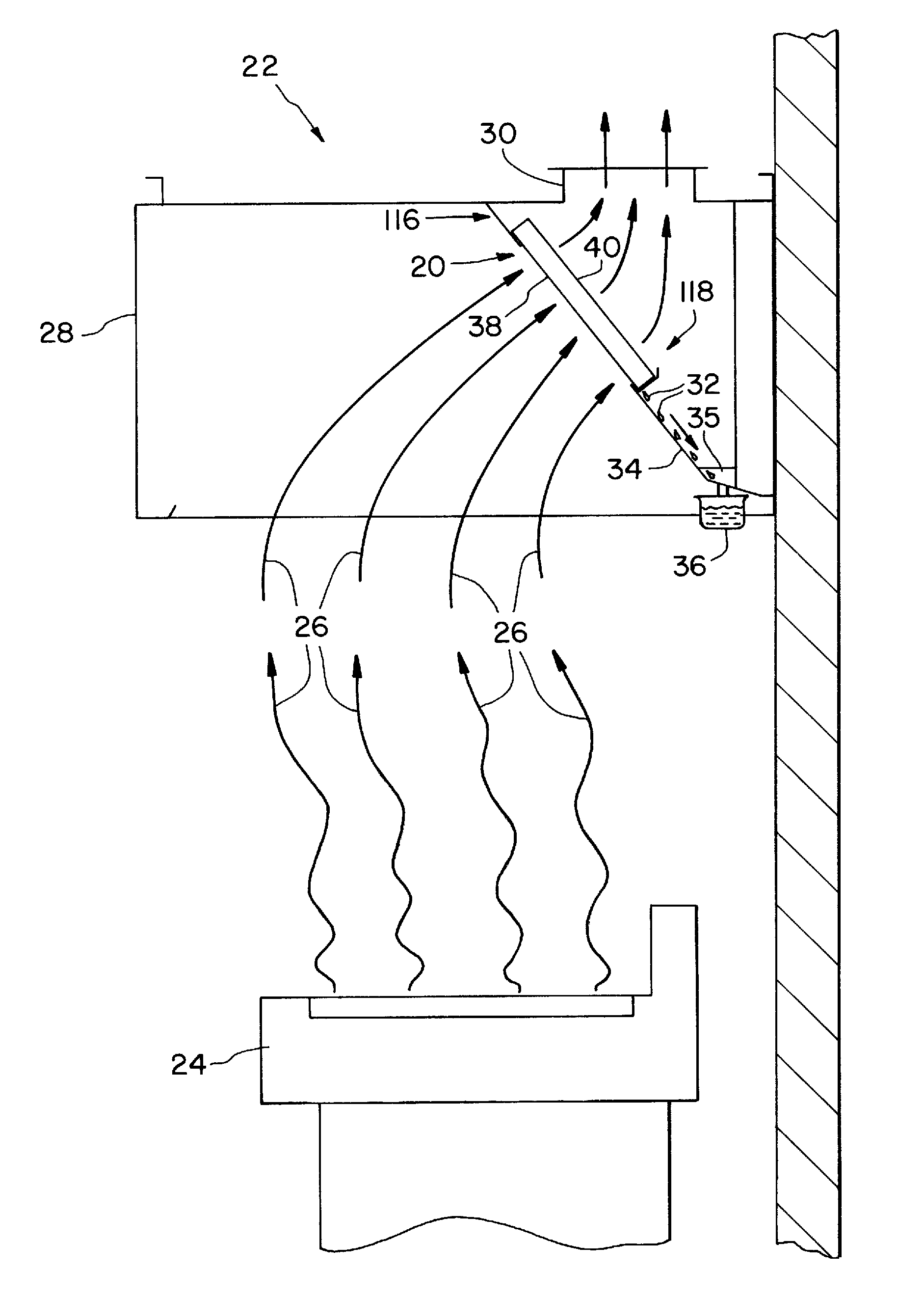
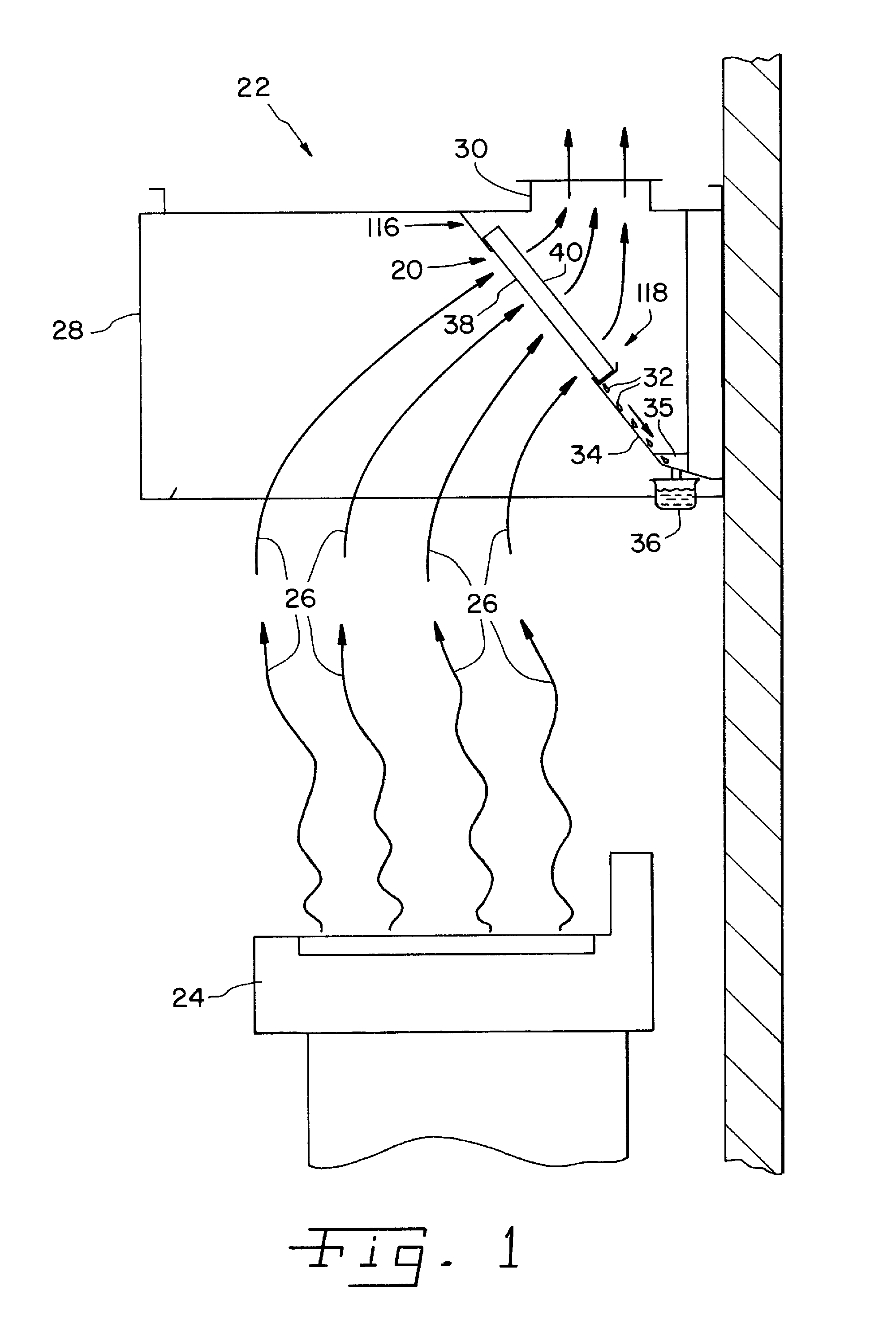
[0034]Referring now to the drawings more specifically, and particularly to FIG. 1, an impact filter 20 in accordance with the present invention is shown. Impact filter 20 can be used in an exhaust air cleaning system 22 above a cooking appliance 24, such as a stove, cook top, griddle or other appliance, which produces hot air, steam, grease-laden cooking vapors, combustion products, and solid and liquid vapors and particulates of various types and compositions, all indicted by arrows 26. Filter 20 is installed at an angle in an air-confining pathway, such as a hood or plenum 28 in flow communication with a duct 30. Grease 32 collected by filter 20 flows from filter 20 along a chute 34 to a collection gutter 35 extending substantially normal to the flow direction of grease 32 from filter 20 over chute 34. Gutter 35 is angled from one end thereof to an opposite end thereof to empty into a drain or cup 36 which can drain automatically or continuously, or can be emptied manually. Filter...


PUM

PropertyMeasurementUnit
Sizeaaaaaaaaaa
Areaaaaaaaaaaa
Distanceaaaaaaaaaa

Abstract

An impact filter suitable for a kitchen exhaust hood is provided with a grease trap to capture grease particles and channel the particles away. The trap can be of different configurations. The filter can be used in various system layouts.

Description

CROSS-REFERENCE TO RELATED APPLICATIONS[0001]The present regular U.S. patent application claims the benefits of U.S. Provisional Application Ser. No. 60 / 857,961 filed on Nov. 10, 2006.FIELD OF THE INVENTION[0002]The present invention relates generally to filters and screens for removing grease and other contaminants from an air stream, and more particularly, the invention pertains to filters for kitchen exhaust hoods used over cooking appliances.BACKGROUND OF THE INVENTION[0003]It is known to provide exhaust hoods above cooking areas to remove smoke, steam and odors from kitchens. The high temperature air exhausted from a cooking area can be laden heavily with grease and other contaminants. It is desirable to remove the grease and other contaminants before the air is released into the atmosphere so that clean air is exhausted. Further, it is desirable to remove a substantial portion of such contaminants early in the exhaust system so that only a minimal amount of contaminants deposi...

Claims


Application Information

Patent Timeline
IPC IPC(8): B01D45/08B01D53/00B03C3/011B03C3/38
CPCF24C15/2035B01D45/08Y10S55/30Y10S55/36
Inventor KWOK, KUI-CHIUROBISON, RUSSELL
Owner ILLINOIS TOOL WORKS INC
Why Eureka
Try Eureka