Flow Control Device

a flow control and diaphragm technology, applied in the direction of fluid pressure control, diaphragm valves, valve housings, etc., can solve the problems of affecting the flow rate control device, the damage of the valve body and the valve seat, and the damage of the diaphragm, so as to prevent the leakage of fluid between the closing portion and the cylindrical portion, prevent the damage of the flexible separation means, and prevent the damage of the first and second flexible separation means

Active Publication Date: 2008-05-15
SURPASS IND
View PDF12 Cites 18 Cited by
  • Summary
  • Abstract
  • Description
  • Claims
  • Application Information

AI Technical Summary

Benefits of technology

[0049]Further, according to the ninth aspect, it is possible to provide an advantage that leakage of fluid from between the closing portion and the cylindrical portion can be prevented.
[0050]Further, according to the tenth aspect, it is possible to provide an advantage that damage of the flexible separation means, which is caused by fluid of high temperature and pressure, can be prevented.
[0051]Further, according to the eleventh aspect, it is possible to provide an advantage that damage of the first and the second flexible separation means can be prevented by the elastic member.
[0052]Further, according to the twelfth aspect, it ...

Problems solved by technology

Accordingly, when the flow rate control device is used to adjust the flow rate of fluid, over a long period of time, temperature and pressure of which are high, for example, to adjust the flow rate of steam, there is a...

Method used


Image

  • Flow Control Device
  • Flow Control Device
  • Flow Control Device

Examples


first embodiment

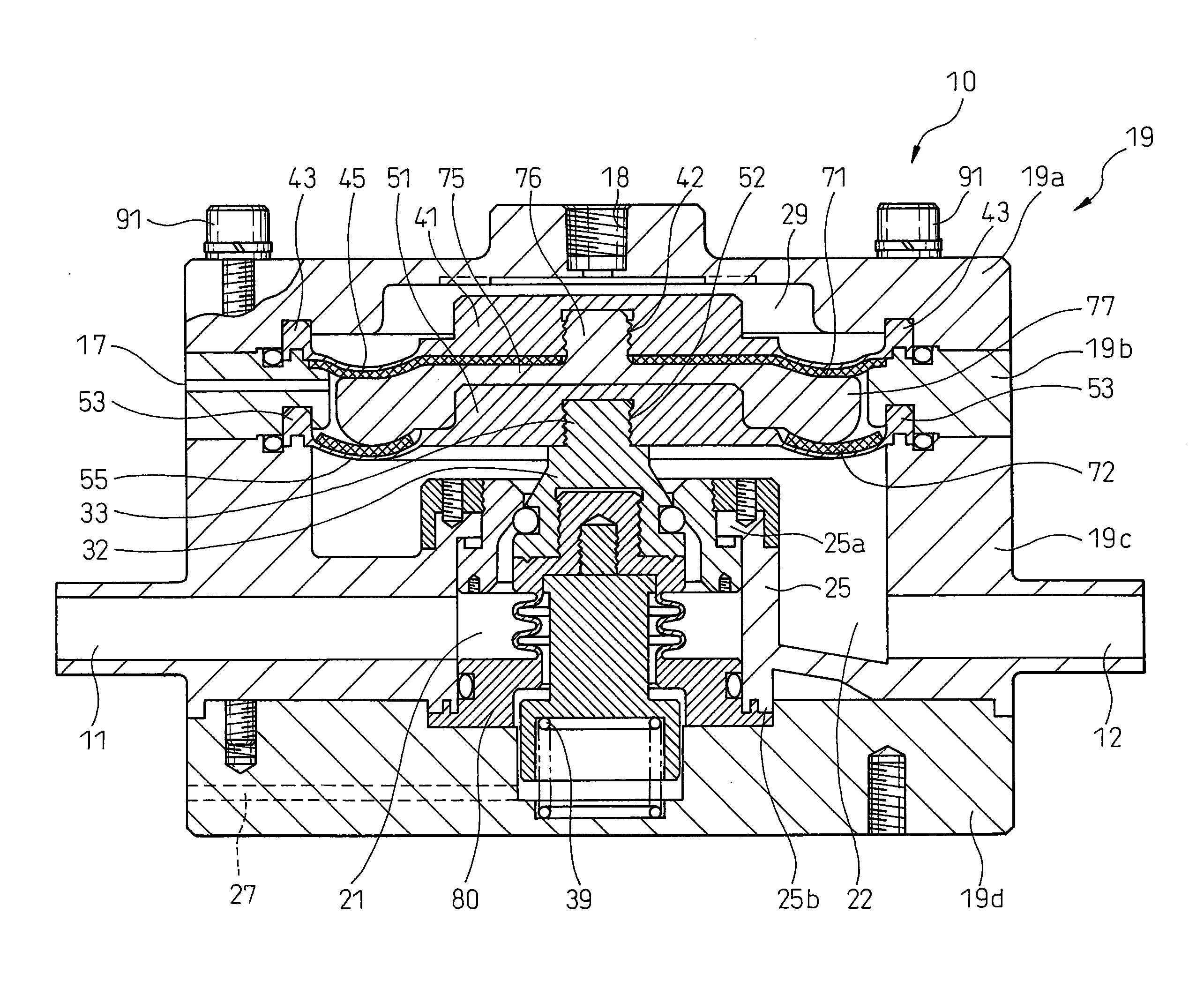
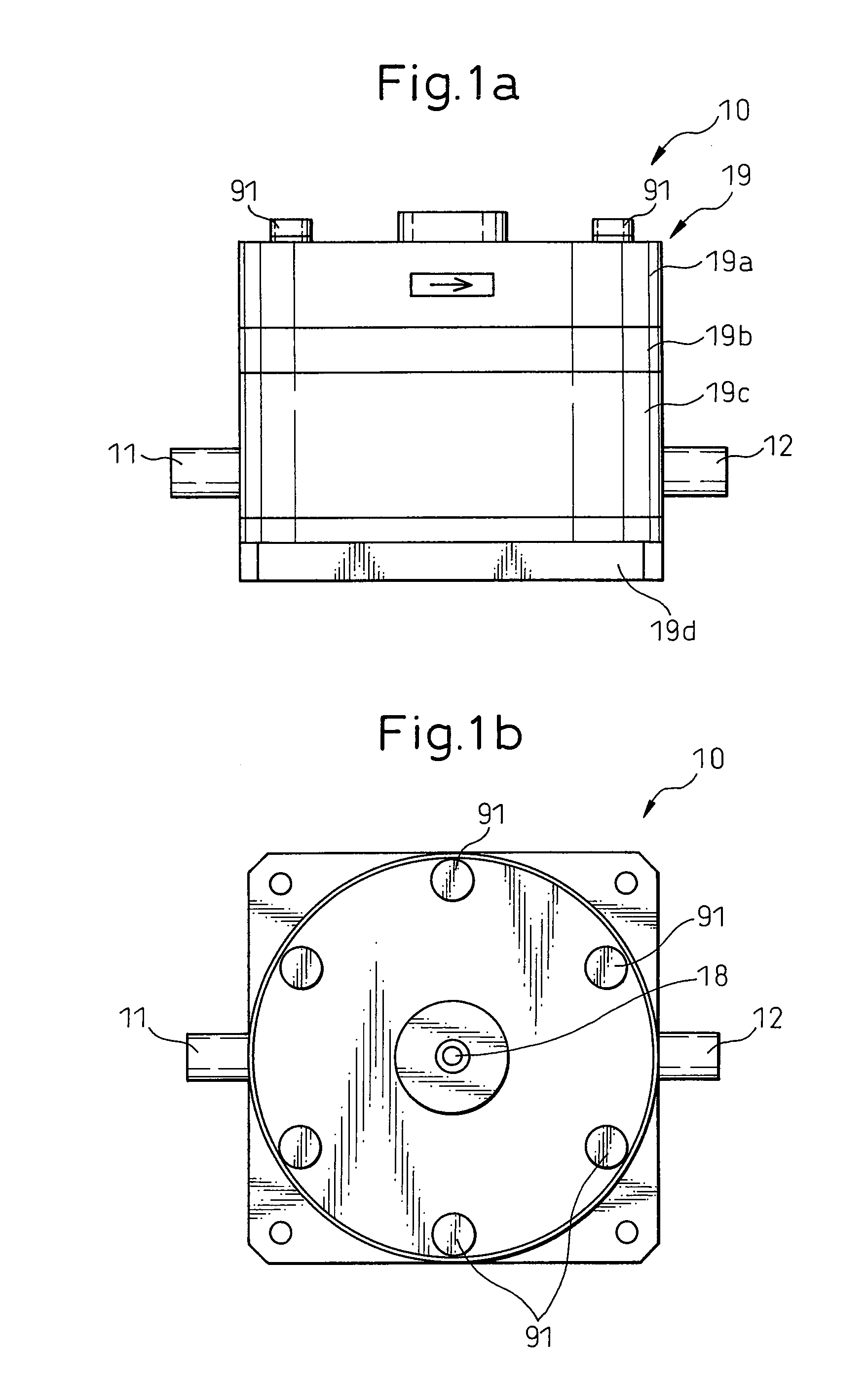
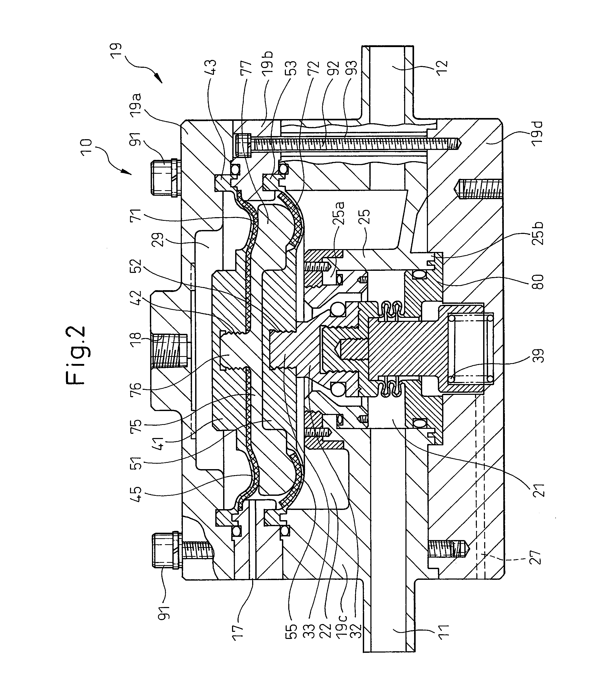
[0071]FIGS. 2 and 3 are sectional side views respectively showing a state of opening the valve and closing the valve of the flow rate control device of the present invention. As can be seen from FIGS. 1 to 3, a plurality of screws 91, which are arranged at regular intervals in the circumferential direction, attach and support parts 19a to 19d of the housing. As shown in the drawing, when the housing annular portion 19b and the housing bottom portion 19d are attached by the other screws 92, the housing barrel portion 19c between the housing annular portion 19b and the housing bottom portion 19d, can be also supported. A pipe 93 is arranged around the barrel portion of the screw 92 in FIG. 2.

[0072]As shown in FIGS. 2 and 3, the inlet port 11 is communicated with a first chamber 21 of a cylindrical portion 25, which is formed integrally with the housing barrel portion 19c. The outlet port 12 is communicated with a second chamber 22 which is formed in the housing barrel portion 19c. The...

third embodiment

[0113]FIG. 7a is a sectional side view showing a state of opening a valve of the flow rate control device 10″ of the present invention. FIG. 7b is an end face view showing the flow rate control device shown in FIG. 7a. In the embodiment shown in FIG. 7a, an under cover 95 is provided, which covers the closing portion 80 from the lower side. The under cover 95 is formed into a substantial cup-shape. The under cover 95 includes: an end portion 96a composing a bottom of the cup; and a sleeve 96b, on the inner circumferential face of which a screw thread is formed, composing a circumferential face of the cup. It is preferable that the under cover 95 be made of a material, the rigidity of which is high, for example, it is preferable that the under cover 95 be made of stainless steel SUS304, etc.

[0114]In the third embodiment, in a bottom portion of the housing barrel portion 19c, a partial annular groove 97 is formed in such a manner that the partial annular groove 97 surrounds the cylind...


PUM


Abstract

A flow control device is provided comprising:
a housing (19) including a first chamber (21) communicated with an inlet port (11) and a second chamber (22) communicated with an outlet port (12); a cylindrical portion (25), which extends in the second chamber, for communicating the first chamber with the second chamber; a valve seat (61) provided at a forward end portion (25a) of the cylindrical portion; and a valve body (32) for opening and closing the valve seat, wherein at least one of the valve seat and the valve body is made of a material, the heat deformation of which is smaller than that of material composing the cylindrical portion. Due to the foregoing, it is possible to stably adjust the flow rate of a fluid of a high temperature and pressure. A pressure chamber (29), which is communicated with the second chamber and provided with a pressure port (18), may be arranged in the housing. A first and second flexible separation means (41, 51), which are connected to each other, for separating the second chamber and the pressure chamber from each other may be provided and a bed (75) arranged between the first and the second flexible separation means may be also provided. A reinforcement member (90) may be embedded in the cylindrical portion (25).

Description

TECHNICAL FIELD[0001]The present invention relates to a flow control device for controlling the flow rate of a fluid. Especially, the present invention relates to a flow control device for controlling the flow rate of steam of high temperature and pressure.BACKGROUND ART[0002]At the time of manufacturing semiconductors, especially at the time of cleaning wafers, it is necessary to supply a highly pure fluid, for example, highly pure hydrochloric acid by a desired flow rate. Therefore, according to the prior art, a flow rate control device shown in FIG. 8, that is, a flow regulating valve is used to control the flow rate of fluid to be supplied.[0003]FIG. 8 is a sectional view showing a flow rate control device of the prior art, such as disclosed in Japanese Unexamined Patent Publication No. 2004-162774. A housing 190 of the flow rate control device 100 is made of resin. On the outside of the housing 190, an inlet port 110 and an outlet port 120 for fluid are respectively arranged. T...

Claims


Application Information

Patent Timeline
IPC IPC(8): F16K27/02F16K31/26F16K7/17
CPCF16K41/10F16K31/1268G05D16/0652G05D16/185Y10T137/7737Y10T137/7762Y10T137/782F16K7/17F16K27/02F16K31/126
Inventor IGARASHI, HIROKI
Owner SURPASS IND
Why Eureka
Try Eureka