Bottle and cap with Anti-glug feature

a technology of bottle cap and anti-glug, which is applied in the direction of caps, containers preventing decay, instruments, etc., can solve the problems of glugging, irregular flow, splashing and slow pouring, and the problem of more pronounced problems, so as to achieve precise positioning of the cap and effectively seal the bottle

Active Publication Date: 2008-05-15
RWACHSBERG HLDG
View PDF7 Cites 23 Cited by
  • Summary
  • Abstract
  • Description
  • Claims
  • Application Information

AI Technical Summary

Benefits of technology

[0007]An object of the present invention is to provide a bottle and cap which may be of the type having an elongate neck and a narrow mouth, with features that prevent or minimizes glugging while liquid is being poured from the bottle, in particular if the bottle is not angled overly steeply nor fully inverted during pouring.
[0008]In one aspect, the invention relates to a combination of bottle and cap, the bottle comprising a body with an upstanding neck for receiving a removable cap. The body includes an elongate, vertically-oriented hollow handle having upper and lower ends, the upper end joining the body at or adjacent to the neck, with the lower portion adjoining the body at a lower region of the body. The handle is spaced apart from the body, to permit the user to easily grip the handle. The hollow interior of the handle forms an air conduit which communicates at its upper and lower end with the interior of the body, to permit a flow of air through the neck opening, via the interior of the handle, to a lower region of the interior of the container. The hollow handle thus effectively forms an air channel leading from the bottle neck or adjacent thereto, terminating at a lower region of the bottle interior.
[0010]The cap preferably fastens to the body neck via a conventional screw threading, although it is preferable that the threads are pitched relatively steeply so as to permit reasonably precise positioning of the cap relative to the body when screwed thereto. Alternatively, the cap may be fastened by other means or may be non-removable from the body, for example, with the bottle and cap being moulded as a single structure, although it is contemplated that in most cases the cap will be removable. The cap may comprise a generally tubular skirt, the wall of which is preferably internally screw-threaded for mating with external threads on the bottle body. A crown partially covers the cap body and optionally a removable or openable cap cover is provided, such as a flip open cover which covers the crown when closed. The cover is optional but it is expected that for most uses the cover will be provided. Preferably, the cap cover is joined to the cap body via a flexible strip which hinges the cover to the body so as to permanently join the cover to the body to prevent the user from mislaying the cover. The cover may snap-lock to the cap body so as to effectively seal the bottle. The crown which partly covers the upper end of the cap includes first and second openings, for dispensing liquid and permitting an intake of air, respectively, during pouring. The first opening is preferably at least partly surrounded by an upstanding wall to channel the flow of liquid during pouring. The second opening may consist of a partially annular-shaped opening which partly surrounds the first opening. The second opening is preferably semi-annular, i.e., consisting of approximately a curved slot extending circumferentially approximately 180 degrees. Preferably, the first and second openings merge together, for example by including a channel within the crown between the first and second openings. The channel may be located at the base of a gap within the upstanding wall. The cover effectively seals both the first and second openings when closed.
[0011]The cap is configured for attachment to the container body so as to position the second opening generally adjacent to the handle, while the first opening is opposed to the handle to form a pour spout for the liquid. For example, if the cap fastens to the body by a screw-threaded attachment, the threads may be pitched reasonably steeply so as to permit the cap to be consistently positioned with a reasonable degree of precision when screwed to the bottle. When thus positioned, the second opening is close to the upper end of the air conduit opening from the handle into the bottle. The second opening effectively forms an air inlet through which air enters as liquid exits the first opening during pouring. The incoming air is channeled into the hollow handle interior with minimal interference with the outflowing liquid.
[0012]According to another aspect, the bottle body includes recesses to enhance the user's grip on the bottle. Preferably, a face of the bottle opposed to the handle includes is scalloped inwardly with a horizontally disposed recess extending across the face of the bottle adjacent the lower edge of the bottle. On or more additional recesses may be provided on the side faces of the bottle on either side of the scalloped recess.

Problems solved by technology

However, they can suffer the drawback of “glugging” when the user pours liquid too rapidly.
This occurs when the outgoing liquid blocks the passage of incoming air, resulting in irregular flow, splashing and slow pouring.
This problem tends to be more pronounced with larger containers which hold relatively large liquid volumes such as those which hold greater than one litre, and in particular if the liquid is relatively viscous, such as liquid soap or the like.
As a result, there is a greater chance that one of the closures will be left unopened or not properly closed after use.
As well, many popular container shapes do not readily accommodate the widely spaced apart secondary opening required for this design, for example containers having an elongate, narrow neck and sloping shoulders.
However, prior art arrangements of this type tend not to be very effective, since the close spacing of the two openings in these arrangements has been ineffective at preventing glugging.
However, since the container has a narrow mouth, the dual openings are of necessity relatively close together, which results in glugging if the liquid is poured too rapidly.
Existing containers, in particular those with narrow necks and mouths, are intrinsically limited in the spacing that is possible between dual openings within the container opening or cap.

Method used


Image

  • Bottle and cap with Anti-glug feature
  • Bottle and cap with Anti-glug feature
  • Bottle and cap with Anti-glug feature

Examples


Embodiment Construction

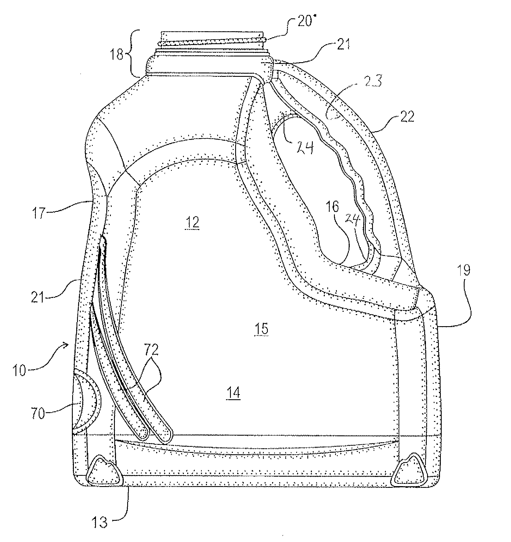
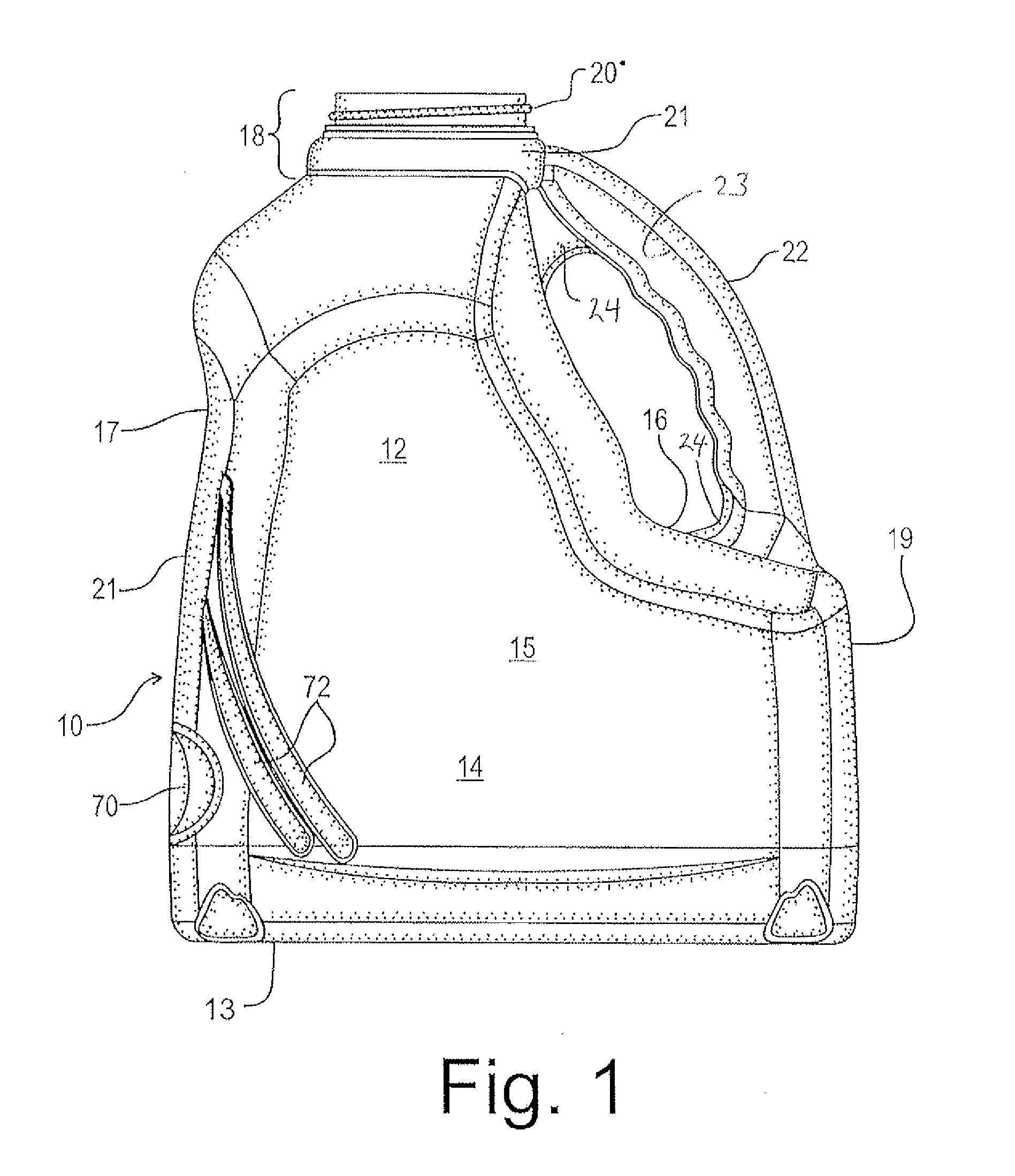
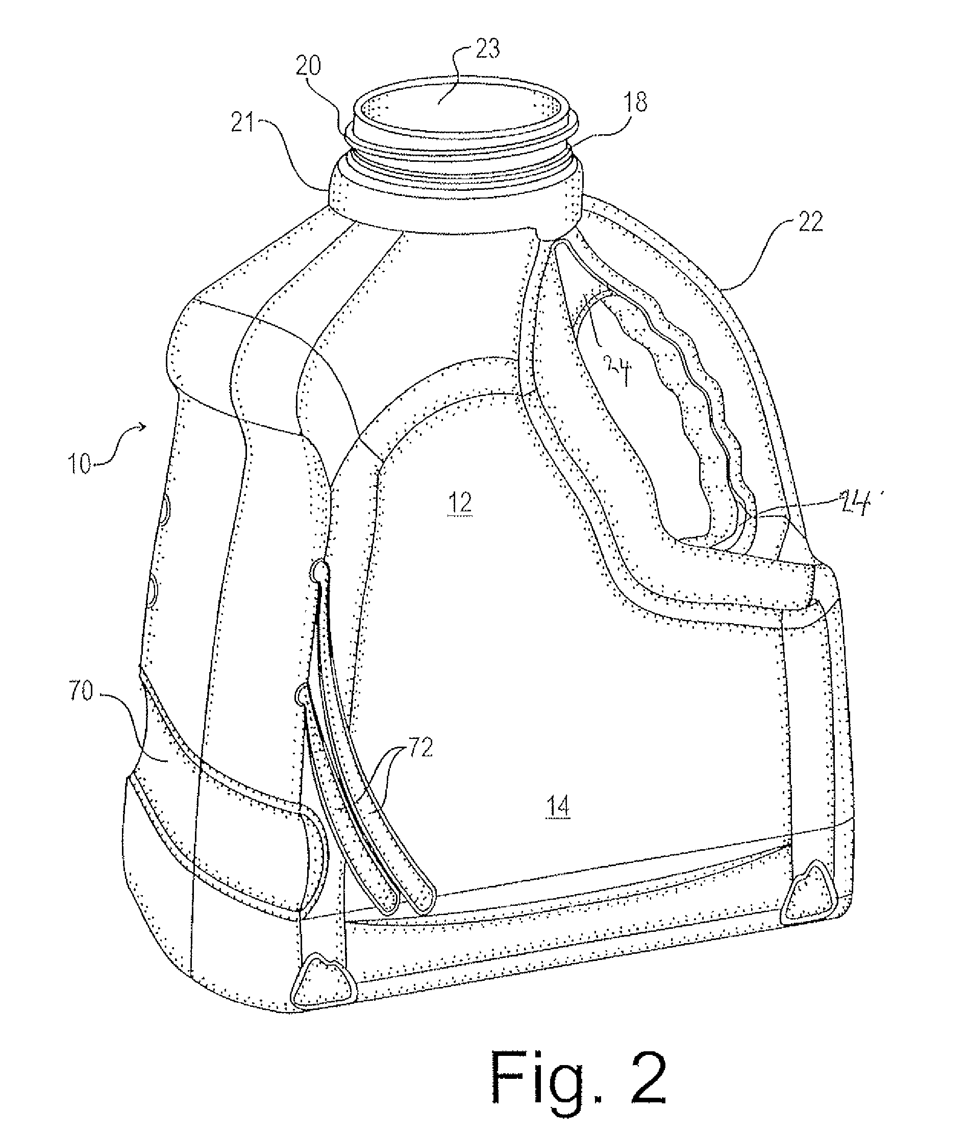
[0022]Referring to the figures, with particular reference to FIG. 1, the bottle 10 comprises moulded plastic which may comprise any conventional, suitably rigid or semi-rigid plastic, having a hollow interior for holding a liquid. For ease of description, the bottle is arbitrarily divided into upper and lower regions 12 and 14 respectively. The upper region 12 is inwardly-stepped from the lower region 14 at a shoulder 16 so as to provide a cutaway portion or recess on one side of the bottle to accommodate the user's hand when gripping the handle, described below. The upper region 12 tapers inwardly towards an elongate upstanding neck 18. The upper portion of the neck having external screw threads 20. The collar 21 is larger in diameter than the neck 18; since the air passage, described below, communicates with the bottle interior at the collar 21, the increased diameter of the collar serves to improve airflow characteristics. The lower portion of the neck 18 comprises a collar 21 wh...


PUM


Abstract

The invention relates to a combination of bottle and cap for dispensing a liquid. The bottle includes a narrow neck and a hollow handle. The hollow interior of the handle communicates at its upper and lower end with the interior of the body, to permit a flow of air through the neck opening, via the interior of the handle, to a lower region within the interior of the container so as to minimize glugging during pouring. The cap comprises a cap body attachable to the neck of the bottle. The cap includes on its crown first and second openings, for dispensing liquid and intake of air, respectively. The cap is configured to attach to the container body so as to position the second opening generally facing the handle, while the first opening is opposed to the handle. During pouring, air flows into the second opening within the cap as liquid exits the first opening, with the inflowing air being channeled into the hollow handle interior with minimal interference with the outflowing liquid so as to introduce air into the interior of the body to displace the liquid being poured from the bottle.

Description

PRIORITY[0001]This application claims priority to Canadian Patent Application No. 2,567,706, filed on Nov. 10, 2006, the contents of which are hereby incorporated by reference.FIELD OF THE INVENTION[0002]The invention relates to hand-held containers for holding a pourable liquid, and in particular to narrow-necked containers which include a means to introduce air into the interior during pouring in order to reduce the glugging that normally occurs if liquid is poured too rapidly, in particular if the liquid is highly viscous.BACKGROUND OF THE INVENTION[0003]Bottles and other liquid-holding containers are often provided with a relatively narrow neck and mouth, making them convenient to handle and pour liquid therefrom. However, they can suffer the drawback of “glugging” when the user pours liquid too rapidly. This occurs when the outgoing liquid blocks the passage of incoming air, resulting in irregular flow, splashing and slow pouring. This problem tends to be more pronounced with l...

Claims


Application Information

Patent Timeline
IPC IPC(8): B65D23/10B65D41/00
CPCB65D25/40B65D47/32B65D47/0842
Inventor WACHSBERG, RICHARD
Owner RWACHSBERG HLDG
Why Eureka
Try Eureka