Humidifying fan

a fan and fan body technology, applied in the field of humidification fans, can solve the problems of large defects, inability to keep the quality of water stable, and the effect of working effectively in a small spa

Active Publication Date: 2008-05-15
KUO TONG ELECTRICAL TECH (HUIZHOU) CO LTD
View PDF22 Cites 16 Cited by
  • Summary
  • Abstract
  • Description
  • Claims
  • Application Information

AI Technical Summary

Benefits of technology

[0010]The objective of this invention is to offer a humidifying fan able to blow air blended with a certain amount of moisture to lower temperature in a room, keeping a user feel comfortable.
[0015]4. The fan device consists of a front cover, a rear cover, blades installed in the front cover and a power element set inside the rear cover functioning to blow air blended with the atomized vapor for reducing the air temperature.

Problems solved by technology

But, it can only works effectively in a small space.
But, its defects are a big size, its water tank to be separated from its fan to become a weird appearance and a pump needed to suck the water in the water tank to form a complicated structure.
But, the quality of the water cannot be kept stable as the spraying nozzles may become abnormal after functioning a period of time.
The defects are that the ultra-sonic device is expensive and has a complicated structure.
The defect is that the water sprayer cannot atomize water satisfactorily.

Method used


Image

  • Humidifying fan
  • Humidifying fan
  • Humidifying fan

Examples


Embodiment Construction

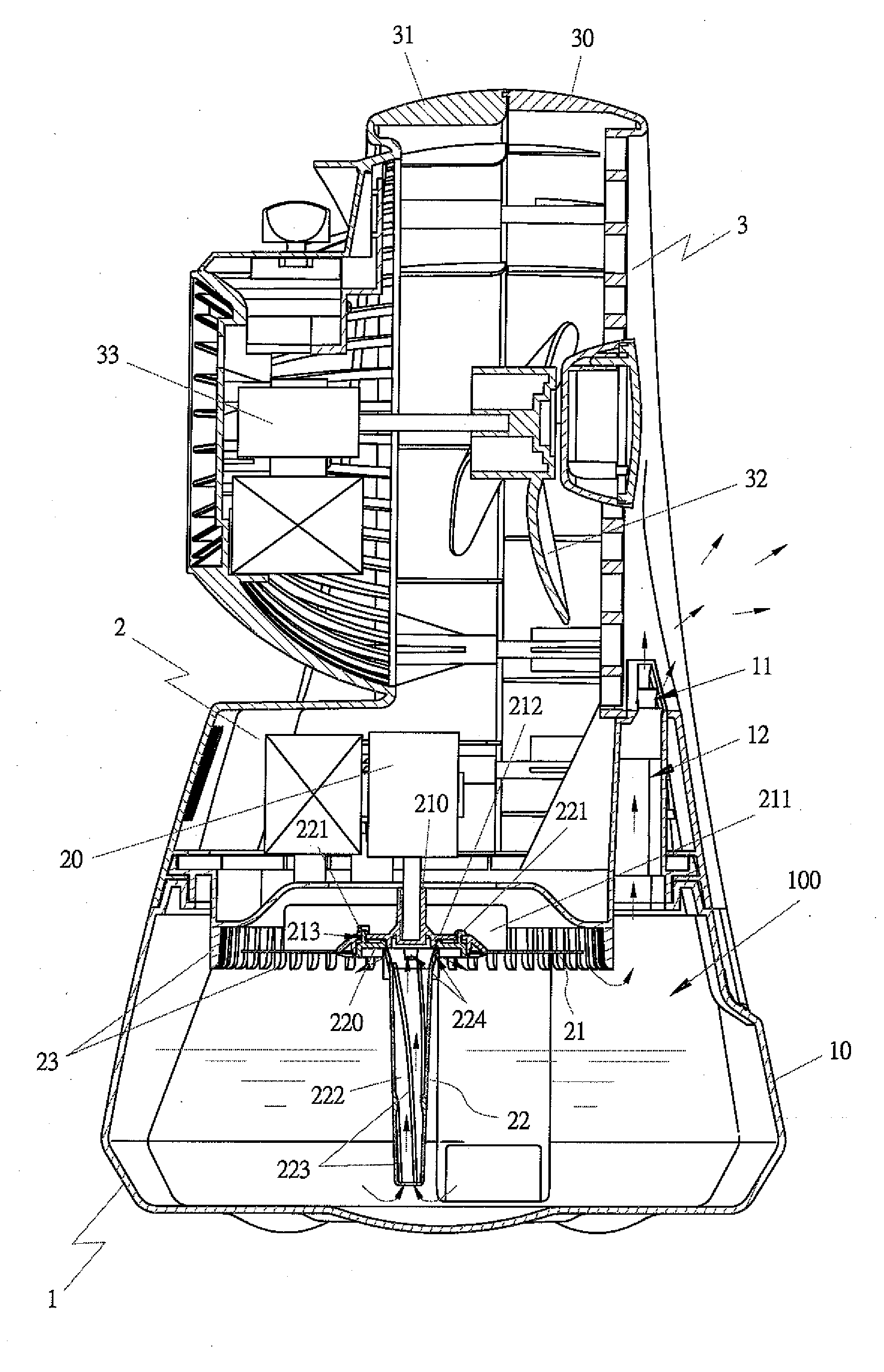
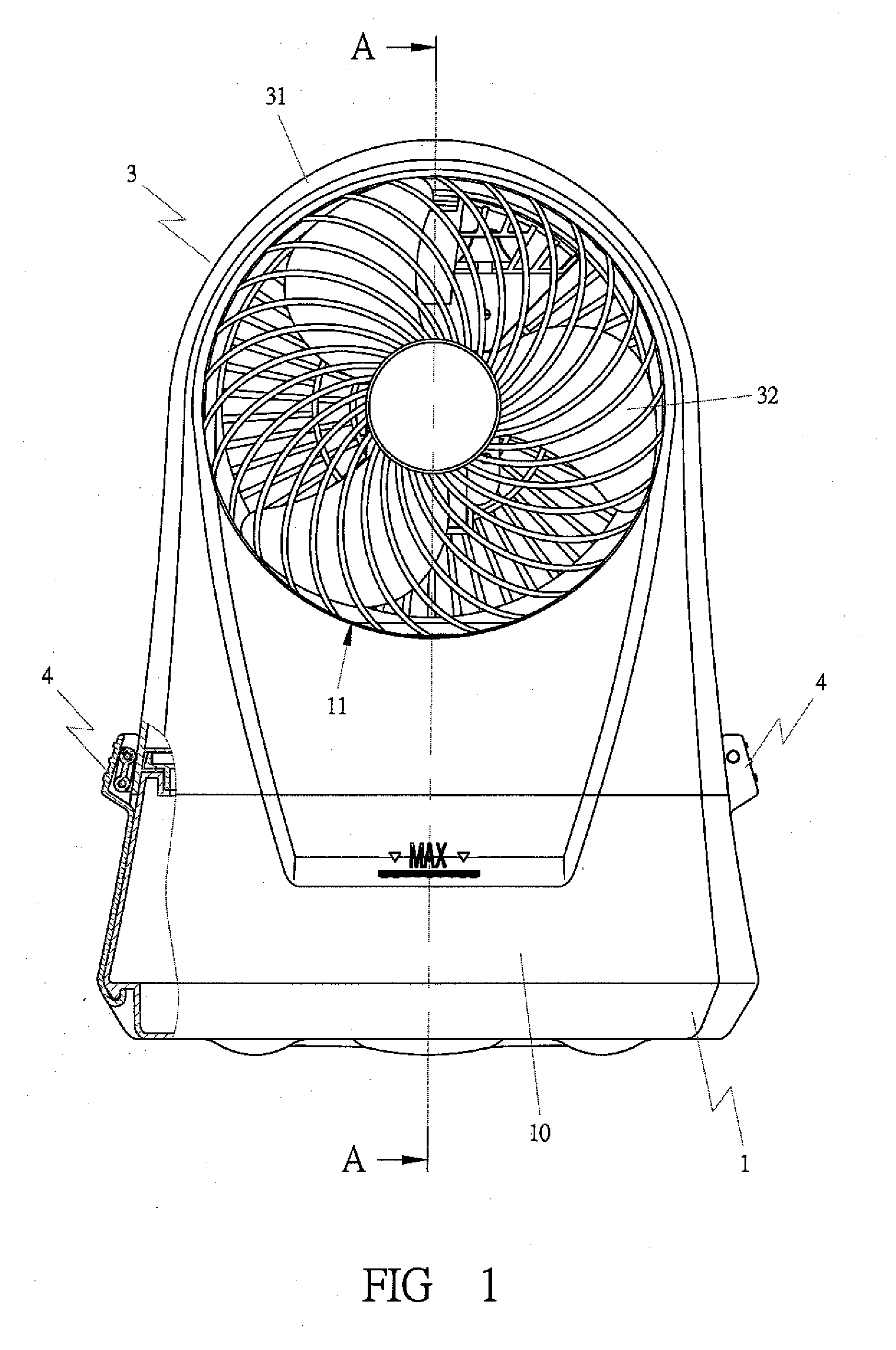
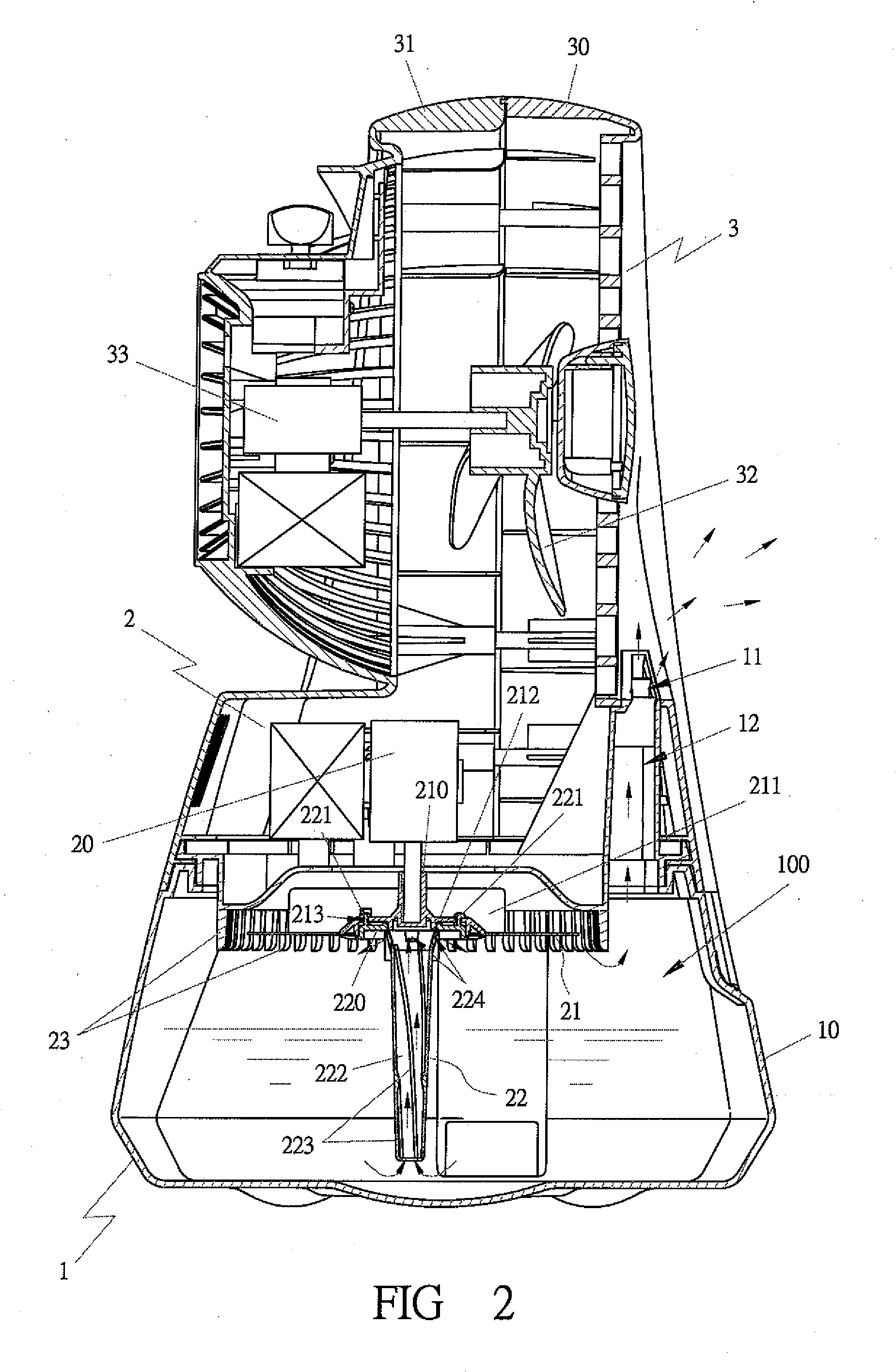
[0027]As shown in FIGS. 1 and 2, a preferred embodiment of a humidifying fan in the present invention includes at least a base 1, a water swinging device 2 and a fan device 3.

[0028]The base 1 is provided with a water tank 10 having a capacity depending on the size of a humidifying fan, for storing an appropriate amount of water or other liquids. The water tank 10 has an empty space 100 formed in its upper portion and provided with a water-spraying hole 11 connected with the water tank 10 through a passage 12.

[0029]The water swinging device 2 is composed of a power element 20, a water swinging fan 21, a suction tube 22 and a fur comb 23. The power element 20 is preferably a motor, but can also be other rotary power elements. The water swinging fan 21 installed in the empty space 100 of the water tank 10 is fixed with the axis of the power element 20 by its axial base 210 and provided with plural spiral blades 211, shown in FIGS. 3 and 4, and a fixing base 212 set under the axial base...


PUM

PropertyMeasurementUnit
temperatureaaaaaaaaaa
relative humidityaaaaaaaaaa
sizeaaaaaaaaaa

Abstract

A humidifying fan includes a base, a water swinging device and a fan device. The base has a water tank for storing an appropriate amount of water or other liquids, and an atomized water hole. The water swinging device has a power element and a water swinging fan connected with a suction tube extending in the water tank and having slots in its inner wall and plural water exits. When water is sucked up to spray through the exits, it is dispersed by the swinging fan to get atomized. But, a large number of droplets without atomized are to attach on a fur comb set around the swinging fan and then drop in the water tank. The fan device consisting of blades and power element is to blow and spread the atomized water for cooling air.

Description

BACKGROUND OF THE INVENTION[0001]1. Field of the Invention[0002]This invention relates to a humidifying fan, A particularly to one able to blow air blended with atomized vapor to lower the air temperature in a room. The invention is composed of a base, a water swinging device and a fan device. The base is provided with a water tank for storing water or other liquids. The water swinging device installed above the water tank is provided with a water swinging fan driven by a power element, and a suction tube set under the water swinging fan for sucking the water or the liquids in the water tank to eject out of water exits. Next, the atomized vapor ejected out of the water exits is to be blown by the water swinging fan to shoot out through a water-spraying hole of the water tank and then, blown further by the fan device to spread widely in the air to lower the air temperature.[0003]2. Description of the Prior Art[0004]There are some conventional cooling fans to be described below.[0005]...

Claims


Application Information

Patent Timeline
Patent Type & Authority Applications(United States)
IPC IPC(8): B01F3/04
CPCF24F5/0035Y02B30/545F24F6/16Y02B30/54
Inventor HUANG, CHIN-CHENG
Owner KUO TONG ELECTRICAL TECH (HUIZHOU) CO LTD
Why Eureka
Try Eureka