Direct current measuring apparatus and limiting circuit

Inactive Publication Date: 2008-05-15
ADVANTEST CORP
View PDF2 Cites 13 Cited by
  • Summary
  • Abstract
  • Description
  • Claims
  • Application Information

AI Technical Summary

Benefits of technology

[0053]A fifth aspect of the invention comprises a first D/A converter outputting a voltage corresponding to a set voltage; a main amplifier generating the set voltage based on an output voltage of the first D/A converter to supply a load with the set voltage; a voltage detecting circuit detecting a voltage of the load, a second D/A converter and a third D/A converter respectively generating and outputting a positive and negative voltage as a predetermined limit voltage supplied to the load; a first limiting circuit amplifying a difference between a detection of the voltage detecting circuit and a positive output voltage of the second D/A converter and feeding back the difference to an input side of the main amplifier through a diode; and a second limiting circuit amplifying a difference between a detection of the voltage detecting circuit and a negative output voltage of the third D/A converter and feeding back the difference to an input side of the main amplifier through a diode, wherein, the first and second limiting circuit includes a first and a second negative feedback loop including a feedback resistance and the respective negative feedback loops include either a common capacitor or a common buffer circuit on an output side of each of the limiting circuits.
[0054]A sixth aspect of the invention comprises a first D/A converter o

Problems solved by technology

Accordingly, in the conventional apparatus, at the occasion when a voltage generating part generates a desired voltage,

Method used


Image

  • Direct current measuring apparatus and limiting circuit
  • Direct current measuring apparatus and limiting circuit
  • Direct current measuring apparatus and limiting circuit

Examples


first embodiment

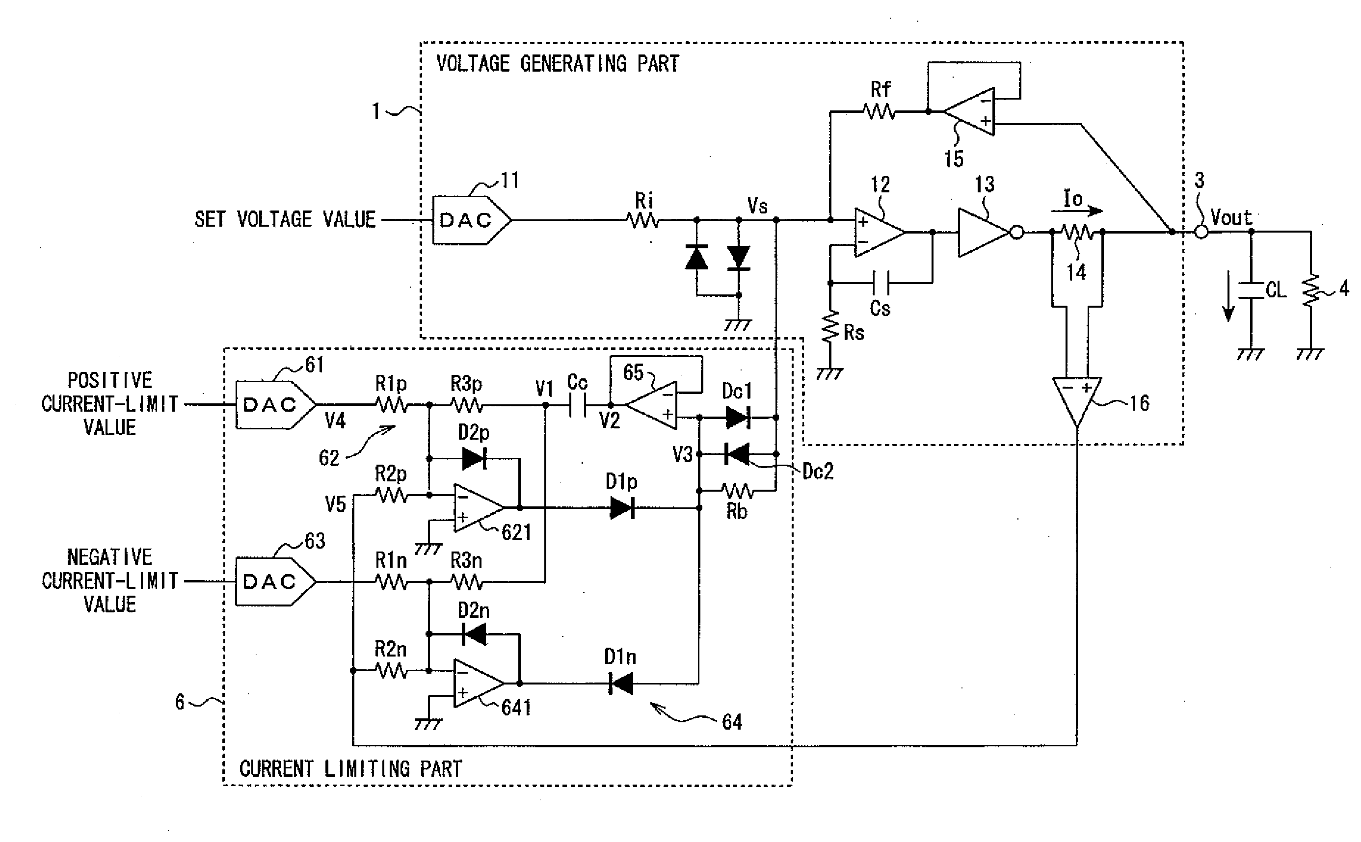
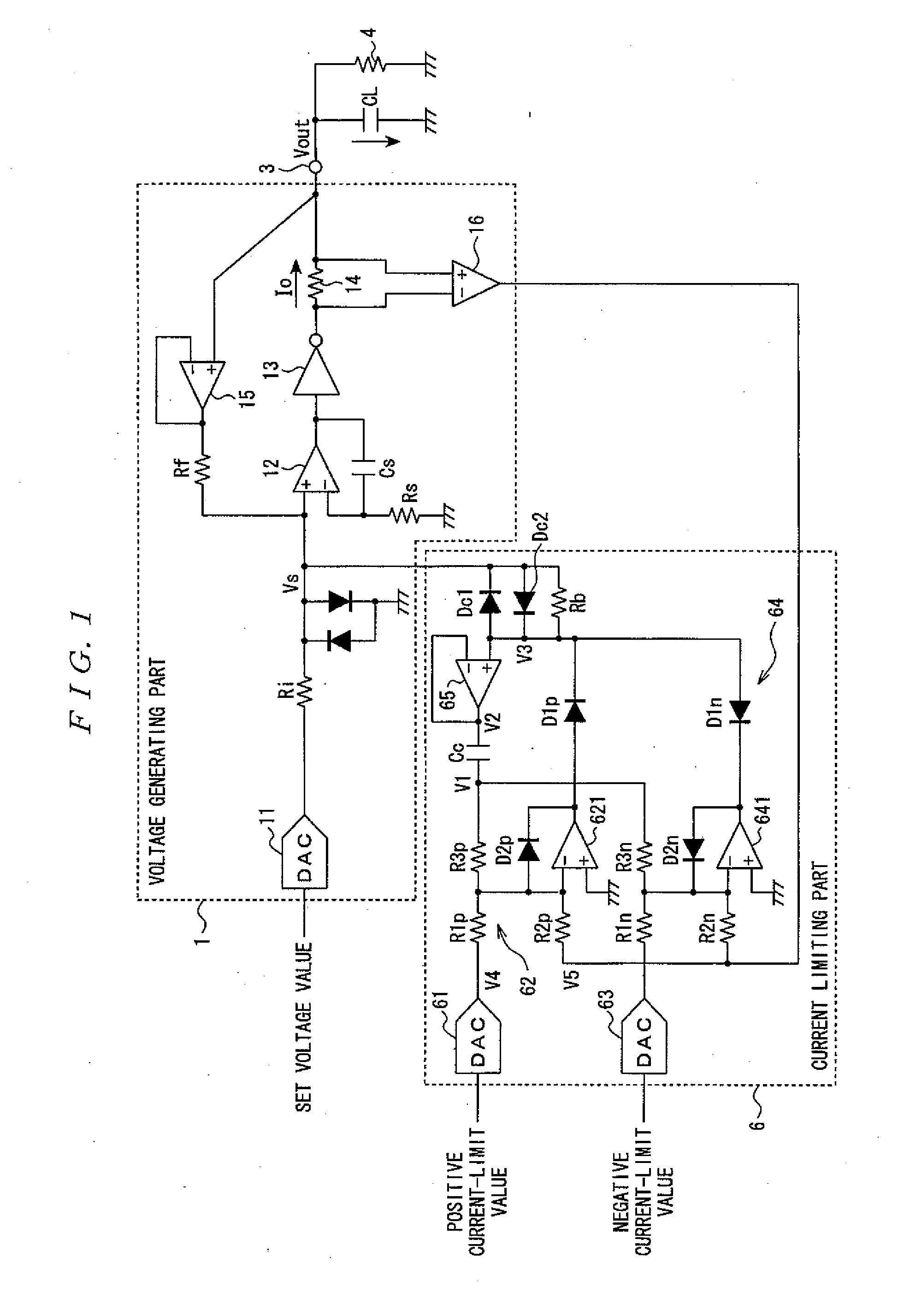
[0079]A first embodiment related to a direct current measuring apparatus applies a desired voltage to a load being a measuring object to measure a current flowing in that load and comprises, as illustrated in FIG. 1, a voltage generating part 1 generating a voltage to be applied to a load 4 being a measuring object; a current limiting part 6 limiting a current flowing in the load 4 to a set value; and an output terminal 3 connected to the load 4.

[0080]The voltage generating part 1 comprises a D / A converter 11; a main amplifier 12; an inverter 13, a current sensing resistor 14; a buffer circuit 15; a differential amplifier 16 and the like. Here, respective components of that voltage generating part 1 is basically the same as the respective components designated with likewise characters in the voltage generating part 1 illustrated in FIG. 7 in configuration thereof.

[0081]The current limiting part 6 comprises a D / A converter 61, a positive side limiting circuit 62, a D / A converter 63 a...

second embodiment

[0123]In the first embodiment illustrated in FIG. 1, either the positive side limiting circuit 62 or the negative side limiting circuit 64 does not operate so that no concurrent operation takes place. Therefore, each negative feedback loop of the positive side limiting circuit 62 and the negative side limiting circuit 64 includes the capacitor Cc in common.

[0124]However, in that case, the capacitor Cc is included in common. Therefore, the respective properties of the positive side limiting circuit 62 and the negative side limiting circuit 64 cannot be made different with the value of the capacitor Cc.

[0125]Therefore, a second embodiment related to the measuring apparatus of the present invention is basically configured likewise the first embodiment illustrated in FIG. 1 and is designed, as illustrated in FIG. 4, so that respectively negative feedback loops of the positive side limiting circuit 62 and the negative side limiting circuit 64 include the capacitors Cc1 and Cc2 independen...

third embodiment

[0129]A third embodiment related to the measuring apparatus of the present invention is basically configured likewise the first embodiment illustrated in FIG. 1 and is designed, as illustrated in FIG. 5, so that respectively negative feedback loops of the positive side limiting circuit 62 and the negative side limiting circuit 64 include the capacitors Cc1 and Cc2 independently and include buffer circuits 65A and 65B independently.

[0130]That is, the negative feedback loop of the positive side limiting circuit 62 includes an independent capacitor Cc1 and the buffer circuit 65A besides the feedback resistance R3p. One end side of the capacitor Cc1 is connected to the feedback resistance R3p and the other end side is connected to an output terminal of the buffer circuit 65A. In addition, the non-inverting input terminal of the buffer circuit 65A is connected to the cathode of the diode D1p.

[0131]In addition, the negative feedback loop of the negative side limiting circuit 64 includes ...


PUM


Abstract

A direct current measuring apparatus includes a voltage generating part generating a voltage to be applied to a load being a measuring object; a current limiting part limiting a current flowing in the load to a set value; and an output terminal connected to the load. The current limiting part includes a D/A converter, a positive side limiting circuit, a D/A converter and a negative side limiting circuit. The positive side limiting circuit includes a negative feedback loop. The negative feedback loop includes a capacitor and a buffer circuit besides the feedback resistance. An output of the positive side limiting circuit positive side limiting circuit is connected to a non-inverting input terminal of the main amplifier through a diode.

Description

PRIORITY CLAIM[0001]This application claims priority from Japanese Patent Application No. 2006-309317, filed with the Japanese Patent Office on Nov. 15, 2006, the contents of which are incorporated herein by reference in its entirety.BACKGROUND OF THE INVENTION[0002]1. Field of the Invention[0003]The present invention relates to a direct current measuring apparatus, which is applied to a direct current test apparatus such as an IC tester, for applying a desired voltage to a load to measure a current flowing through a load or supplying the load with a desired current to measure a voltage across the load, and in particular, to a direct current measuring apparatus capable of limiting an overcurrent flowing through the load and an overvoltage applied to the load.[0004]2. Description of the Related Art[0005]An example of a conventional direct current measuring apparatus of this type is illustrated in FIG. 7.[0006]This direct current measuring apparatus applies a desired voltage to a load...

Claims


Application Information

Patent Timeline
IPC IPC(8): G01R1/28G01R19/25H03L5/00
CPCG01R31/31924G01R19/0092
Inventor KODERA, SATOSHI
Owner ADVANTEST CORP
Why Eureka
Try Eureka