Transparent material inspection system

a technology of transparent materials and inspection systems, applied in the direction of optical properties testing, structural/machine measurement, instruments, etc., can solve the problems of general human error, lack of uniformity, and tediousness of the technique, and achieve the effect of more defects

Inactive Publication Date: 2008-05-15
DUFOUR CHRISTIAN +1
View PDF0 Cites 65 Cited by
  • Summary
  • Abstract
  • Description
  • Claims
  • Application Information

AI Technical Summary

Benefits of technology

[0023]By calibrating the intensity of the pixels of the LCD prior to the inspection procedure, the present invention is generally able to detect

Problems solved by technology

Such a technique is generally prone to human error, lacks uniformity, and furthermore, is particularly tedious.
Understandably, the system is quite limited to specific types of lenses.
Yet, even though all these systems are generally useful for their intended purposes, they are a

Method used


Image

  • Transparent material inspection system
  • Transparent material inspection system

Examples


Embodiment Construction

[0027]A novel system for inspecting transparent material will be described hereinafter. Although the invention is described in terms of specific illustrative embodiments, it is to be understood that the embodiments described herein are by way of example only and that the scope of the invention is not intended to be limited thereby.

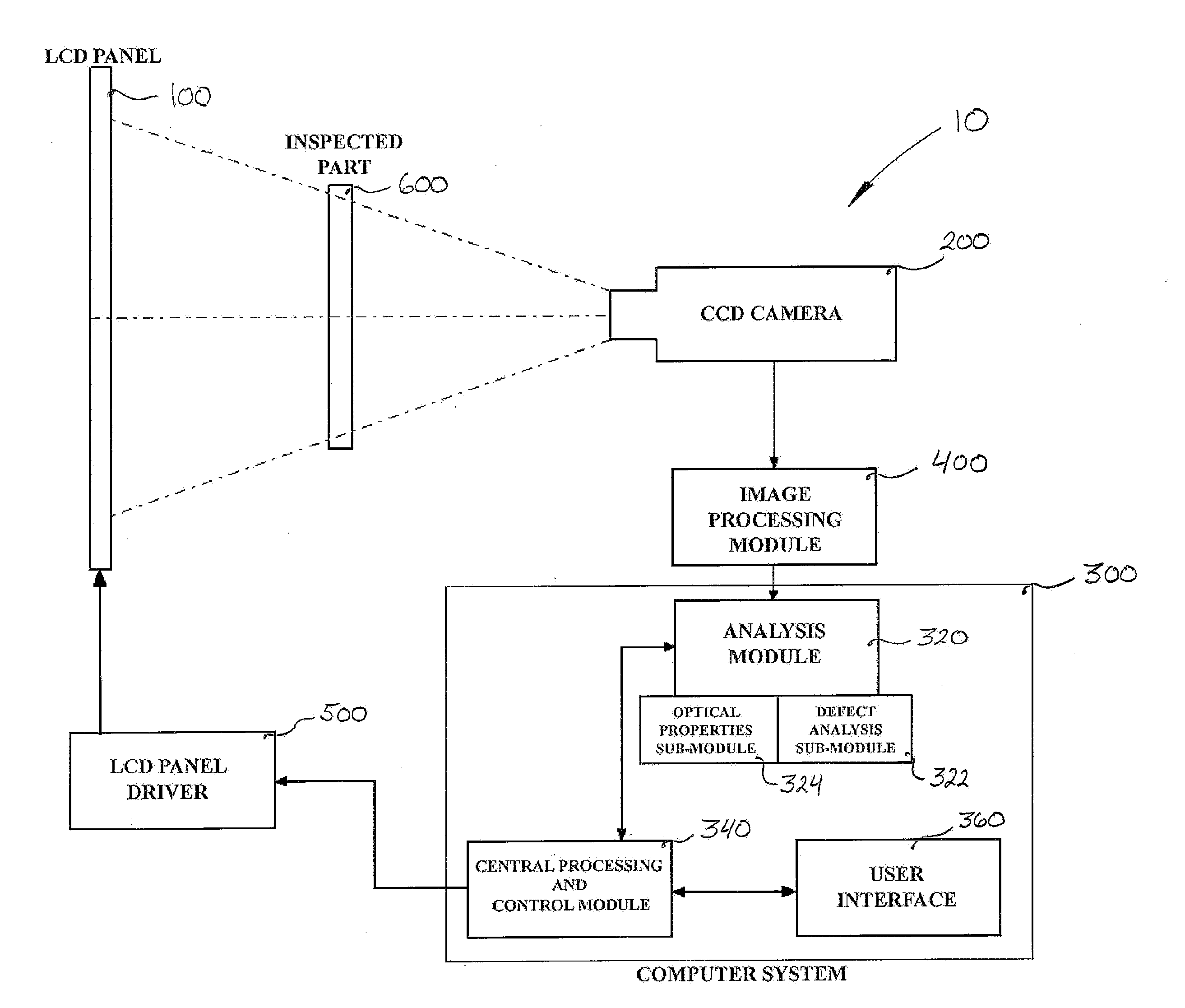
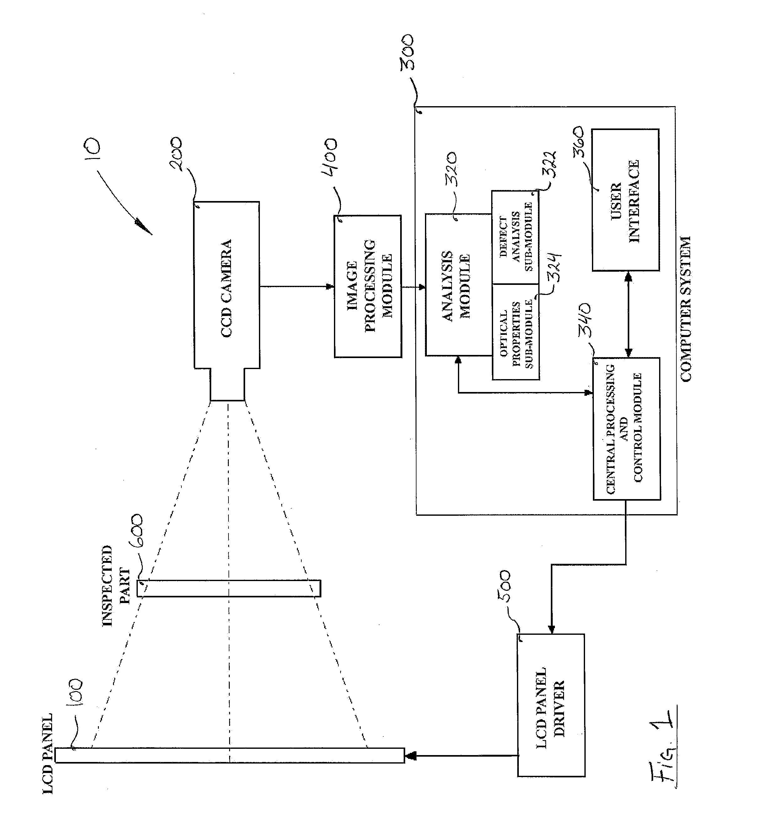
[0028]Referring now to FIG. 1, the inspection system 10 of the present invention generally comprises a LCD panel 100 and a CCD camera 200 facing the LCD. The alignment between the LCD 100 and the CCD 200 can be chosen and changed as required according to any type of inspection.

[0029]The LCD panel 100 is in electronic communication, with wire or wirelessly, with a LCD panel driver 500. Understandably, the LCD panel driver 500 controls the LCD panel 100 and the images projected thereby. Preferably, the LCD panel driver 500 is able to control the intensity of each individual pixel forming the LCD panel 100.

[0030]The CCD camera 200 is in electronic communicati...


PUM


Abstract

A system for the inspection of the optical quality of a part, object or product having a portion comprising transparent material such as ophthalmologic lenses, protective eyewear, visors, eyewear shield and the like is provided. A liquid crystal display (LCD) screen emits variable patterns of light through the transparent part under inspection to a charged coupled device (CCD) camera that captures the image and transmits the image data to an image processing module. The processed image data are then transmitted to an analysis module which then generally measures the dimensions of the part, the transparency, the colour and the optical strength. The analysis module also advantageously detects and measures the presence of dots, stains, scratches, optical distortions, fingerprints, cloudiness and other optical artefacts and/or defects in the transparent material. Accordingly, the patterns emitted by the LCD screen are designed to measure the optical specifications and highlight potential optical defects.

Description

CROSS-REFERENCE TO RELATED APPLICATIONS[0001]There are no cross-related applications.FIELD OF THE INVENTION[0002]This invention relates systems and apparatuses for the inspection of transparent materials such as, but not limited to, lens, eyewear, visors and eyewear shields. More particularly, the present invention relates to systems and apparatuses for the inspection of transparent materials which use charged coupled device (CCD) or similar cameras.BACKGROUND OF THE INVENTION[0003]The testing of transparent material, such as contact lenses and eyewear, for optical properties, quality, colour, flaws and defects has previously been mainly performed by human inspectors who had to manually verify each object. Such a technique is generally prone to human error, lacks uniformity, and furthermore, is particularly tedious. Indeed, the quality of consecutive inspections can vary according to the degree of tiredness of the inspector.[0004]Thus, in order to mitigate the lack of uniformity of ...

Claims


Application Information

Patent Timeline
IPC IPC(8): G01B9/00
CPCG01M11/0228G01M11/0278G01N2021/8835G01N2021/8832G01N21/958
Inventor DUFOUR, CHRISTIANCOTE, JEAN-ROBERT
Owner DUFOUR CHRISTIAN
Why Eureka
Try Eureka