

Magnetic disk drive
- Summary
- Abstract
- Description
- Claims
- Application Information
AI Technical Summary
Benefits of technology
Problems solved by technology
Method used
Image

Examples
first embodiment
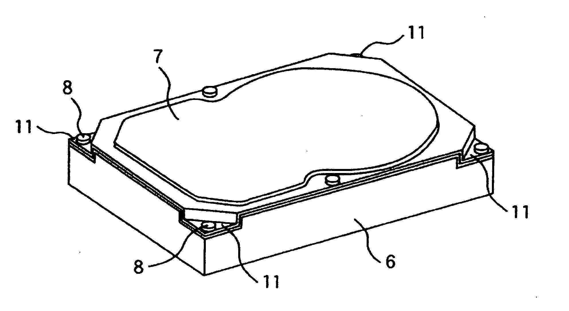
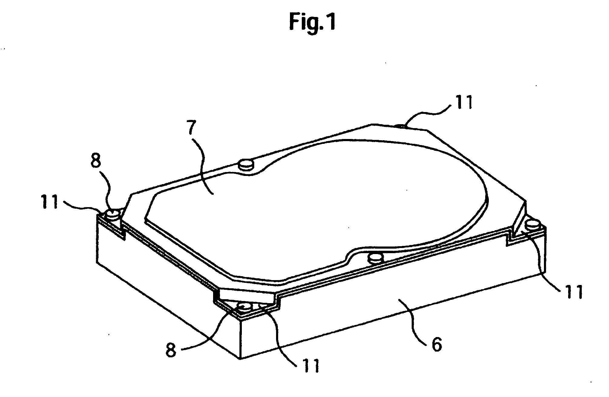
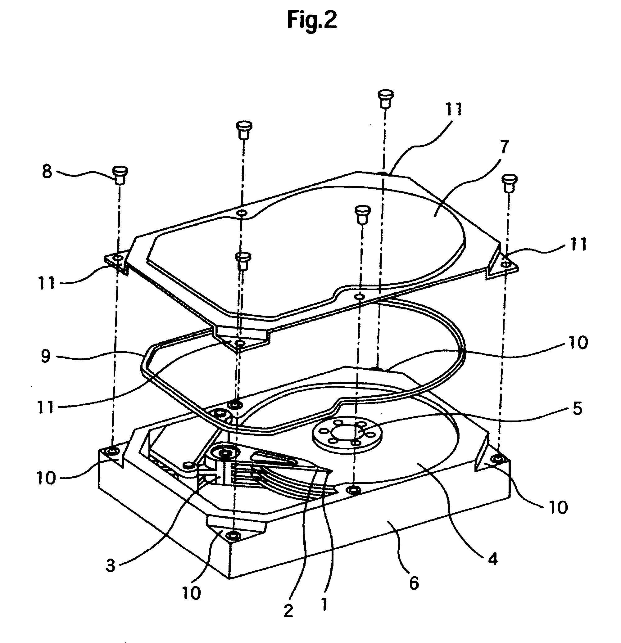
[0029]FIGS. 1 and 2 are a perspective view and a development, respectively, of a magnetic disk drive according to the invention. FIG. 3 is a schematic diagram of a connecting portion of a base and a cover. As shown in FIGS. 1 and 2, a base 6 is one that was formed by aluminum die casting, has a concave, rectangular parallelepiped shape, and is formed with step portions (recesses) 10 at the four corners. The base 6 contains a spindle motor 5, magnetic disks 4 which are attached to the rotary shaft of the spindle motor 5, an access mechanism 3 which supports suspensions 2 which hold magnetic heads 1 at their tips, a head amplifier (not shown) for amplifying a recording signal to be supplied to a magnetic head 1 or a reproduction signal coming from a magnetic head, and other components. A circuit board (not shown) is attached to the back surface of the base 6, and is mounted with an LSI which incorporates a signal processing circuit, a microcontroller for controlling the entire magneti...
second embodiment
[0035] Next, a second embodiment will be described with reference to FIGS. 6 and 7. FIG. 6 is a top view of a magnetic disk drive and shows how a cover is fixed. FIG. 7 is a sectional view taken along line A-A in FIG. 6 and shows a base-cover fixing structure at one corner of a case. The base 20 may be configured in the same manner as in conventional devices and is formed with boss-shaped fixing portions 22 at the corners. The cover 15 is a flat plate of stainless steel or iron and is formed with screw holes 16 at the four corners and two side positions. Plural holes 17 are formed inside the respective screw holes 16. The holes 17 serve to make the rigidity of the corner portions of the cover 15 lower than that of the other portion (i.e., flat portion). As shown in FIG. 7, the holes 17 of the cover 15 are formed so as to be located between a gasket 9 and bolts 8 when the cover 15 is fixed to the base 20. This is to prevent dust from entering the case through the holes 17.
[0036] Also...
PUM
 Abstract
Description
Claims
Application Information