Method and system for transmitting connectivity fault management messages in ethernet,and a node device

a network and fault management technology, applied in the field of telecommunication technologies, can solve the problems that the node of a pbb-te path cannot be implemented by previous nodes, and the connectionless ethernet mechanism cannot be used to monitor pbb-te connection,

Active Publication Date: 2008-05-15
HUAWEI TECH CO LTD
View PDF36 Cites 64 Cited by
  • Summary
  • Abstract
  • Description
  • Claims
  • Application Information

AI Technical Summary

Problems solved by technology

1. Continuity Check (CC) mechanism. The procedure for the CC mechanism is as follows. The Maintenance association End Points (MEPs) periodically send CC messages (CCM) to other MEPs in the same Maintenance Association (MA). If no CC messages have been received from any MEP within 3.5 times of the CC interval, alerts will be generated to notify that there may be some failure on the connection. Information, such as an MEP list and MD level, are preconfigured on the MEP. Faults, such as link failure, misconnection, can be detected by CC mechanism. There are two kinds of CC messages, multicast CC message and Unicast CC message. The multicast CCM is applicable to all types of connection monitoring. The destination address of multicast CC message is a special CFM multicast address. A multicast CC message is broadcast to all other MEPs in the same MA. Unicast CC is applicable to point-to-point connection monitoring. The destination address of unicast CC message is the address of the remote MEP. A unicast CC message is forwarded along a unicast forwarding path.
2. Loopback (LB) mechanism. LB is typically used for fault location A loopback initiator transmits an LB message (LBM) to a destination Maintenance Point (MP). When receiving a LBM, the destination maintenance point will return an LB reply (LBR) to the loopback initiator. If the loopback initiator has not received an expected LBR within a certain period of time, it means that a connectivity fault is present between the loopback initiato

Method used


Image

  • Method and system for transmitting connectivity fault management messages in ethernet,and a node device
  • Method and system for transmitting connectivity fault management messages in ethernet,and a node device
  • Method and system for transmitting connectivity fault management messages in ethernet,and a node device

Examples


embodiment 1

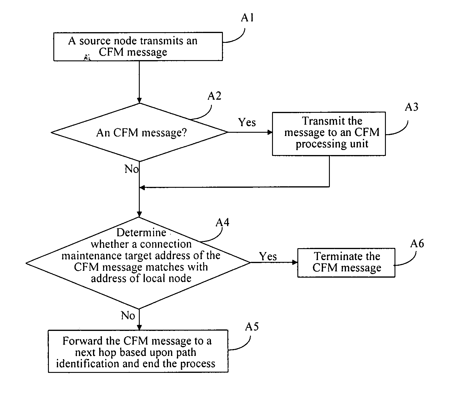
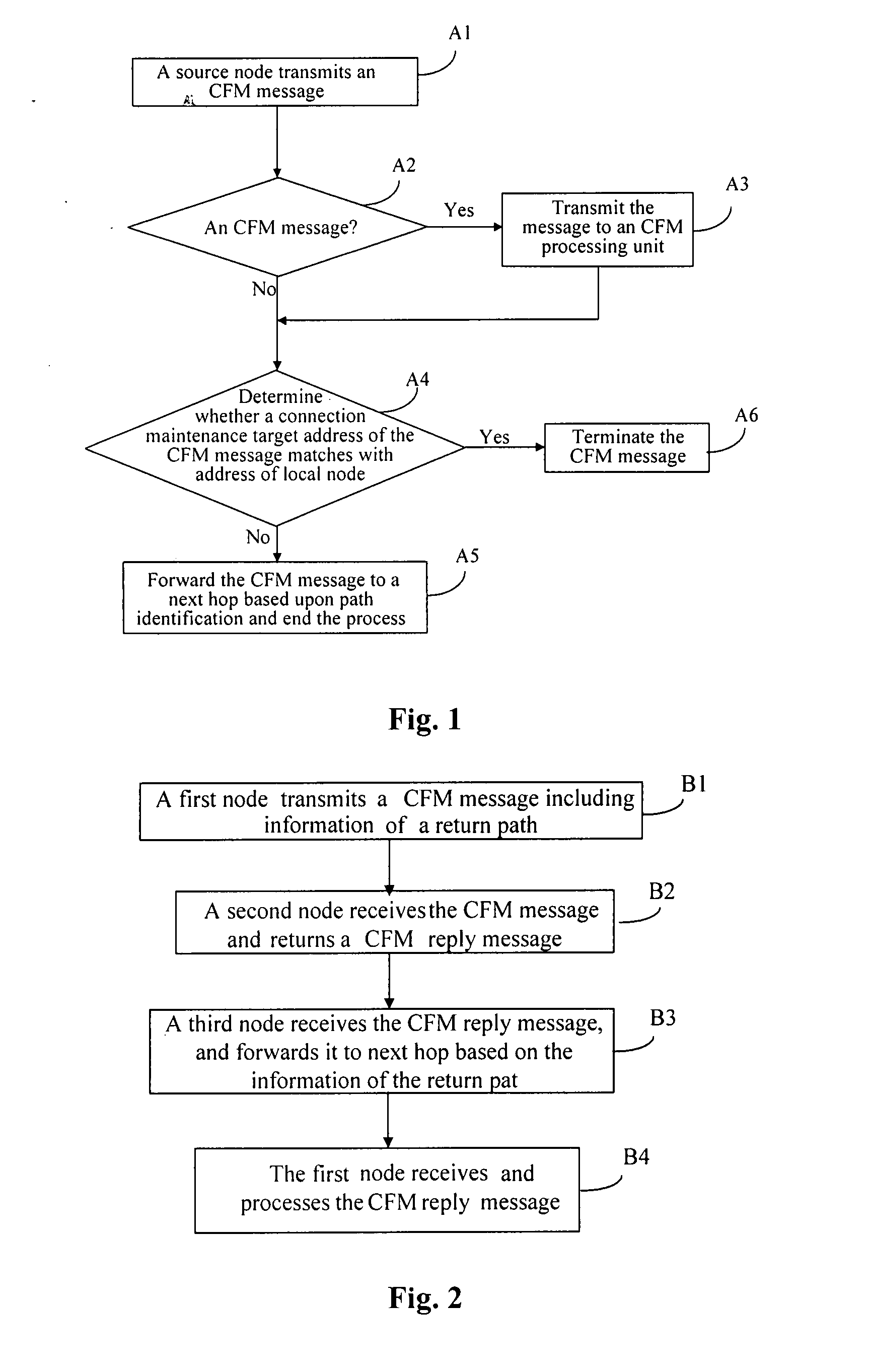
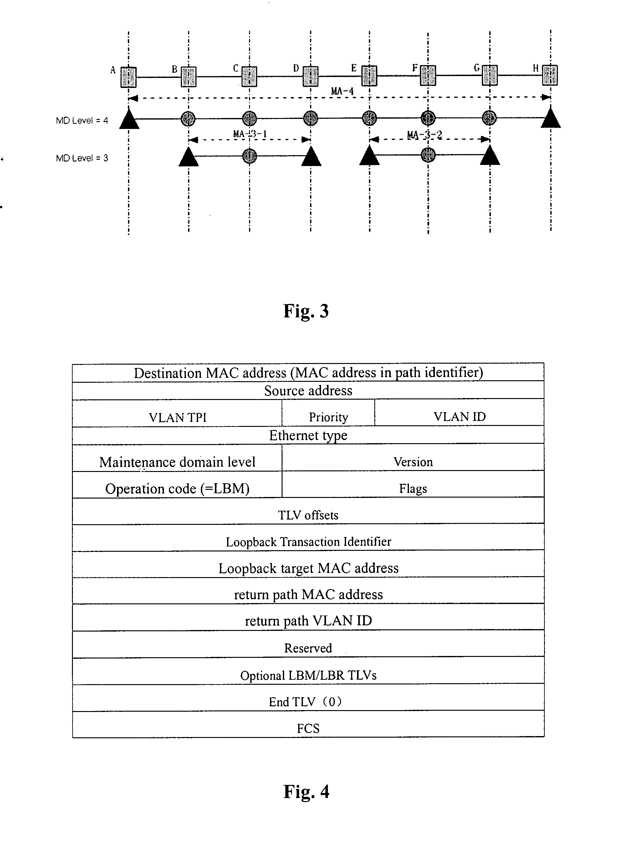
[0055]If a Continuity Check (CC) from node B to node D with MD Level of 3 is required, and a destination MAC address in a CFM message transmitted from a source node is a MAC address of a path including a monitored connection, when the maintenance points of the PBB-TE network are configured as illustrated in FIG. 3, a method for transmitting and processing a connectivity fault management (CFM) message according to an embodiment of the invention is as follows.

[0056]s101, an MEP list, and a time interval t, at which Continuity Check Messages (CCMs) are transmitted, are configured at the destination node D.

[0057]s102, the source node B initiates a CC check, and generates and transmits a CCM to the destination node D at a time interval of t. The CCM is composed of an Ethernet header and a CCM PDU. The Ethernet header includes:

[0058]a destination MAC address, i.e. a path MAC address in path identifier of a path including a monitored connection. There is no dedicated path identifier for B-...

embodiment 2

[0070]If a Continuity Check (CC) from the nodes B to D of MD Level 3 is required, and a destination MAC address in a CFM message transmitted from a source node is a MAC address dedicated for a CFM function, when the maintenance points of the PBB-TE network are configured as illustrated in FIG. 3, a method for transmitting and processing a connectivity fault management message according to the embodiment of the invention is as follows.

[0071]s201, an MEP list, and a time interval t, at which CCMs are transmitted, are configured at the destination node D.

[0072]s202, the source node B initiates a CC check, and, generates and transmits a CCM to the destination node D at a time interval of t. The CCM is composed of an Ethernet header and a CCM PDU. The Ethernet header includes:

[0073]a destination MAC address, i.e. a MAC address dedicated for a CFM / CCM function. All the nodes shall support the processing for this address;

[0074]a VLAN ID, i.e. a virtual local area network identifier which i...

embodiment 3

[0088]If a Loopback (LB) check from the node A to node D of MD Level 4 is required, and a destination MAC address in a CFM message transmitted from a source node is a path MAC address in path identifier of a path including a monitored connection, when the maintenance points of the PBB-TE network are configured as illustrated in FIG. 3, a method for transmitting and processing a connectivity fault management message according to the embodiment of the invention is as follows.

[0089]s301, the source node A initiates an LB check, and generates and transmits a loopback message (LBM) to the destination node D. The LBM is composed of an LBM Ethernet header and a LBM PDU as described by FIG. 4. The LBM Ethernet header includes:

[0090]a destination MAC address, i.e. a path MAC address in path identifier of a path including a monitored connection. There is no dedicated path identifier for path A-to-D, but the path A-to-D is a part of path A-to-H. Therefore in the LBM, the destination MAC addres...


PUM


Abstract

A method for transmitting a Connectivity Fault Management (CFM) message of Ethernet includes: receiving a CFM message transmitted from a source node, the CFM message including identifier of a path and a connection maintenance target address; determining whether the connection maintenance target address matches address of a receiving node, and if yes, terminating the CFM message; otherwise forwarding the CFM message to a next hop based upon the path identifier of the path. Another method and a system for transmitting a CFM message of Ethernet, a node for transmitting a CFM message of Ethernet, and a node for receiving a CFM message of Ethernet are also disclosed. With the invention, a CFM message may be forwarded according to information of MAC address and VLAN ID of identifier of a path where a monitored service is located, and thus may be forwarded correctly in a PBB-TE network.

Description

[0001]This application claims the priority of the Chinese Patent Application No. 200610137898.2, filed with the Chinese Patent Office on Nov. 9, 2006, entitled “A Method and System for Transmitting Operation Administration and Maintenance Message in Ethernet, and A Node”, and the priority of the PCT Patent Application No. PCT / CN2007 / 070294 filed on Jul. 13, 2007, entitled “Method and System for Transmitting Connectivity Fault Management Message in Ethernet, and A Node device”, the contents of which are incorporated herein by reference in entirety.FIELD OF THE INVENTION[0002]The invention relates to the field of telecommunication technologies, and in particular, to a method and system for connectivity fault management in a network, and a node device.BACKGROUND OF THE INVENTION[0003]The Provider Backbone Bridge Traffic Engineering (PBB-TE) is an Ethernet based solution for provider network. In comparison with a traditional Ethernet, this solution removes the mechanisms of self-learnin...

Claims


Application Information

Patent Timeline
IPC IPC(8): G06F11/07
CPCH04L12/4641H04L43/0811H04L41/06
Inventor LONG, HAODENG, ZHUSHENG
Owner HUAWEI TECH CO LTD
Why Eureka
Try Eureka