Encoding apparatus and encoding method

a technology of encoding apparatus and encoding method, which is applied in the direction of color television with bandwidth reduction, signal generator with optical-mechanical scanning, and signal system with bandwidth reduction, etc., can solve the problems of significant reduction of encoding efficiency and redundant amount of update processing, so as to reduce the amount of calculation processing, and reduce the effect of encoding efficiency

Inactive Publication Date: 2008-05-15
HITACHI LTD
View PDF4 Cites 20 Cited by
  • Summary
  • Abstract
  • Description
  • Claims
  • Application Information

AI Technical Summary

Benefits of technology

[0007] On the other hand, using a temporally distant image as the reference frame of a fast-moving video or a video with large movement generates a problem that the encoding efficiency is significantly decreased.
[0008] In view of the fore going, the present invention reduces the amount of calculation processing in the encoding processing while suppressing a decrease in encoding efficiency.
[0010] The above configuration controls whether or not the reference frame update processing is to be performed and reduces the amount of calculation processing during the encoding processing while suppressing a decrease in encoding efficiency.
[0011] The present invention can reduce the amount of calculation processing during the encoding processing while suppressing a decrease in encoding efficiency.

Problems solved by technology

However, when inter-screen prediction is performed for a slow-moving video or a video with little movement in the prior art, always using the temporally closest image as the reference frame of the video generates a problem that the reference frame update processing involves an amount of calculation that is redundant.
On the other hand, using a temporally distant image as the reference frame of a fast-moving video or a video with large movement generates a problem that the encoding efficiency is significantly decreased.

Method used


Image

  • Encoding apparatus and encoding method
  • Encoding apparatus and encoding method
  • Encoding apparatus and encoding method

Examples


first embodiment

[0037] First, the following describes a first embodiment of the present invention with reference to the drawings. FIG. 5A and FIG. 5B show multiple frames included in moving-image data. FIG. 5A shows an example of the operation of encoding processing in the prior art, and FIG. 5B shows an example of the operation of encoding processing in the first embodiment of the present invention. The picture type is indicated in each frame. An arrow shown in the figure indicates the prediction relation when data is encoded. An arrow indicates that a predicted image for encoding the frame at the end point of the arrow is generated with the frame at the start point of the arrow as the reference image. As shown in FIG. 5A and FIG. 5B, I-pictures and P-pictures are used, but B-pictures are not used, as the picture structure in the first embodiment of the present invention.

[0038] Referring to frames (501)-(507) in FIG. 5A, the following describes a case in the prior art in which the image temporall...

second embodiment

[0107] Next, the following describes a second embodiment of the present invention with reference to the drawings. FIG. 6A to FIG. 6E show multiple frames included in moving-image data. Those figures show an example of the operation of encoding processing in the prior art and an example of the operation of encoding processing in the second embodiment of the present invention. The picture type is indicated in each frame. An arrow shown in the figure indicates the prediction relation when data is encoded. An arrow indicates that a predicted image for encoding the frame at the end point of the arrow is generated with the frame at the start point of the arrow as the reference image. As shown in FIG. 5A and FIG. 5B, the picture structure used in the second embodiment of the present invention includes all of I-pictures, P-pictures, and B-pictures.

[0108] Referring to the frames (601)-(607) in FIG. 6A, the following describes the encoding processing in the prior art in which all of I-pictur...


PUM


Abstract

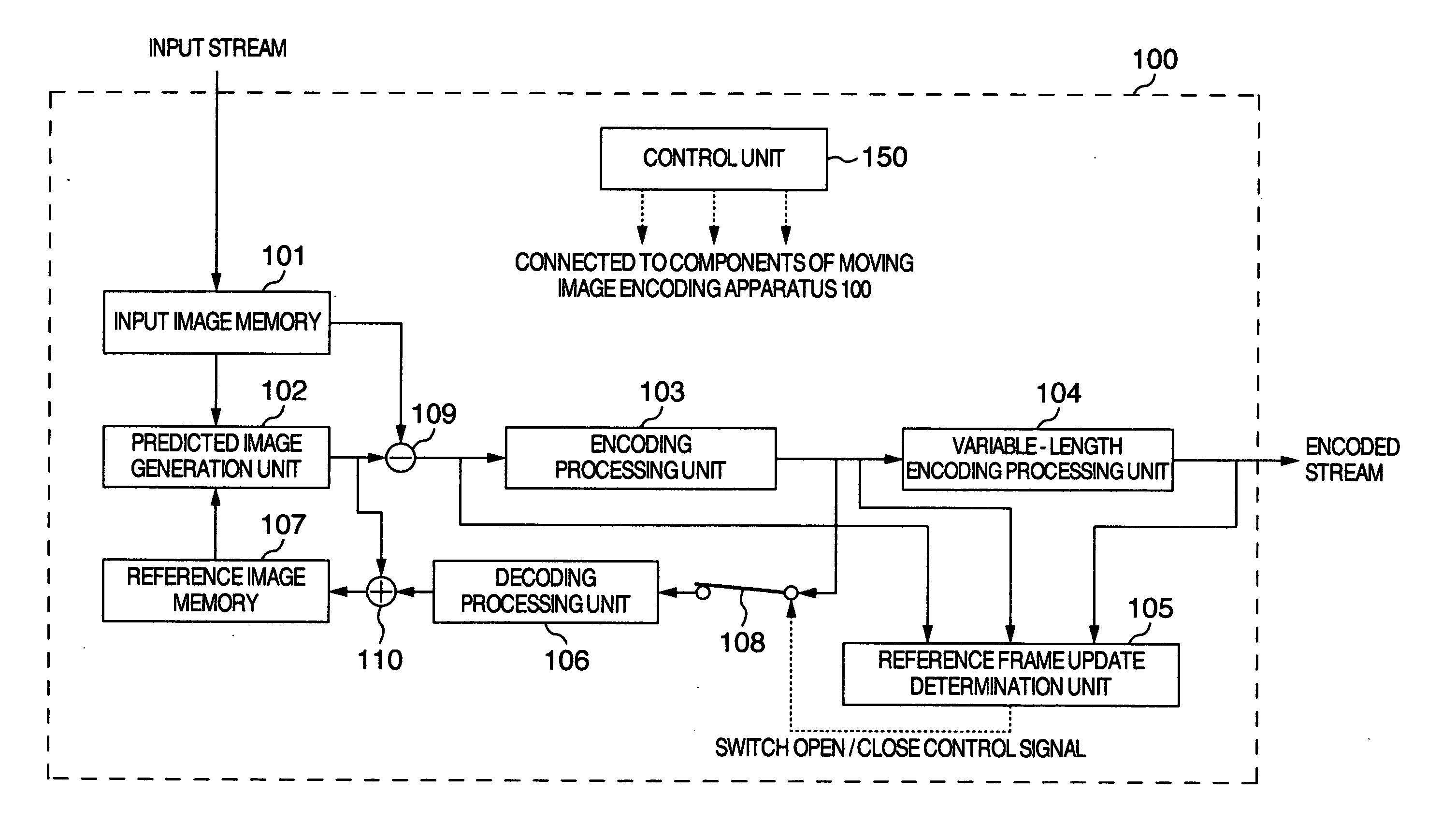
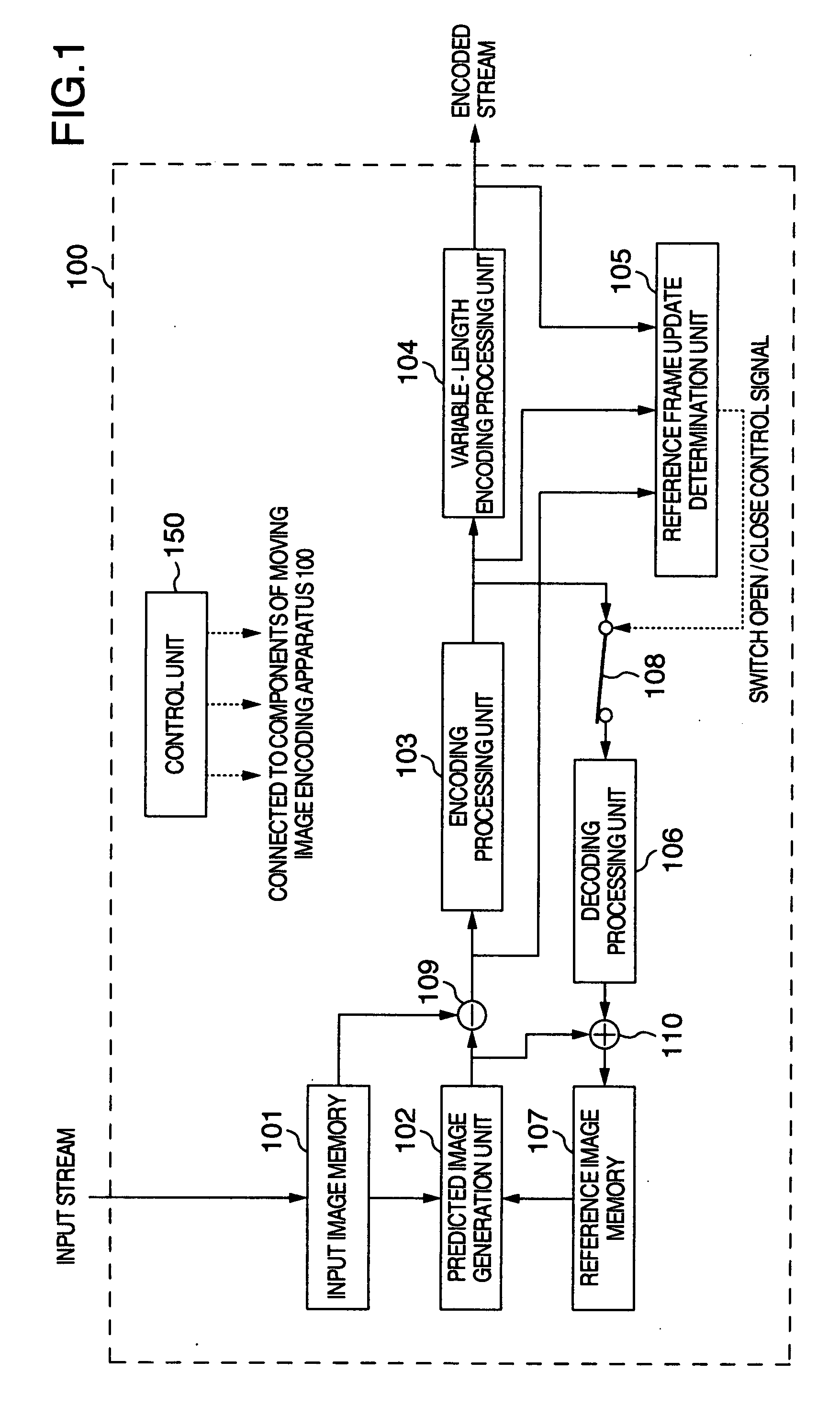
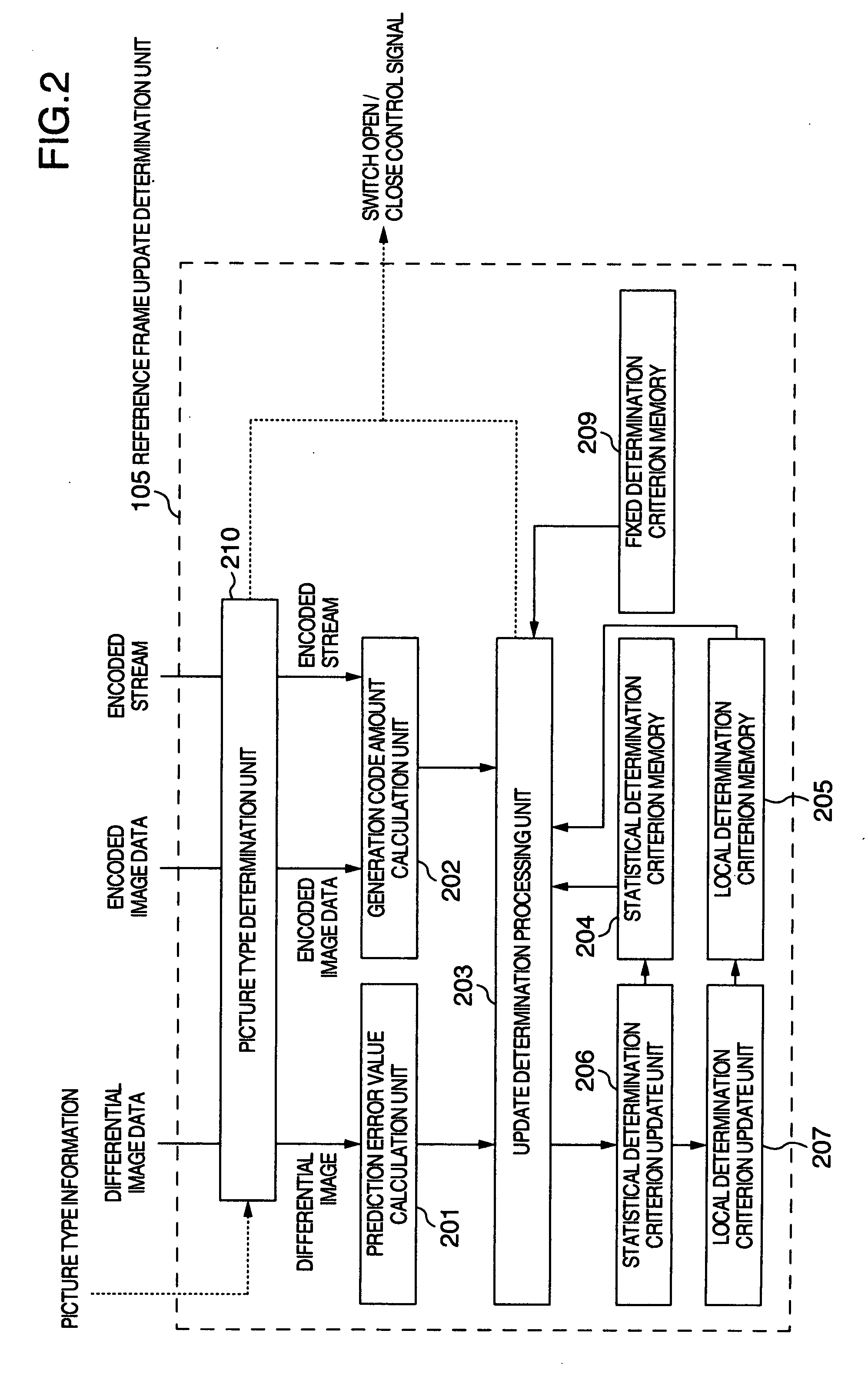
The calculation processing amount of encoding processing is reduced while suppressing a decrease in encoding efficiency. An encoding method includes the steps of generating predicted image data from an image of a predetermined reference frame; generating differential image data from a difference between the predicted image data and image data of one frame of the input image data; performing discrete cosine transformation processing and quantization processing for the differential image data for generating encoded image data; performing variable-length encoding processing for the encoded image data for generating an encoded stream; and performing reference frame update determination processing in which a correlation between the image of the reference frame and the image of the one frame is determined for deciding whether or not the one frame is to be used as a new reference frame.

Description

INCORPORATION BY REFERENCE [0001] The present application claims priority from Japanese application JP2006-306135 filed on Nov. 13, 2006, the content of which is hereby incorporated by reference into this application. BACKGROUND OF THE INVENTION [0002] 1. Field of the Invention [0003] The present invention relates to a technology for encoding a moving image. [0004] 2. Description of the Related Art [0005] In the encoding technology in which predictive images are generated from reference images for encoding a moving image, a technology, such as the one disclosed in US2006 / 0171680 (corresponding to JP-A-2006-217180), is known for determining whether or not an image is to be deleted from the reference image memory. SUMMARY OF THE INVENTION [0006] However, when inter-screen prediction is performed for a slow-moving video or a video with little movement in the prior art, always using the temporally closest image as the reference frame of the video generates a problem that the reference f...

Claims


Application Information

Patent Timeline
Patent Type & Authority Applications(United States)
IPC IPC(8): H04N7/32H04N19/50H04N19/102H04N19/137H04N19/172H04N19/196H04N19/503H04N19/577H04N19/60H04N19/61H04N19/625H04N19/91
CPCH04N19/105H04N19/159H04N19/146H04N19/109H04N19/137H04N19/61
Inventor TAKAHASHI, MASASHIMURAKAMI, TOMOKAZUITO, HIROAKIKARUBE, ISAO
Owner HITACHI LTD
Why Eureka
Try Eureka