System and method for testing leds on a motherboard

a technology of leds and motherboards, applied in the field of system and method for testing leds on a motherboard, can solve the problems of increased complexity, manual testing may likely destroy the pcb, and problems such as led production lines

Inactive Publication Date: 2008-05-15
HON HAI PRECISION IND CO LTD
View PDF8 Cites 9 Cited by
  • Summary
  • Abstract
  • Description
  • Claims
  • Application Information

AI Technical Summary

Benefits of technology

[0007]A system for testing light-emitting diodes (LEDs) on a motherboard includes: a motherboard, an insulating plate, a panel, a camera module and a computer. The insulating plate is positioned on the motherboard and configured with optical fibers for inducing beams sourced from the LEDs. The panel is connected to the insulating plate with the optical fibers, and receives the beams transmitted from the LEDs. The panel includes a corresponding number of transparent bulbs configured for outputting the beams sourced from the LEDs. The camera module is fixed on the panel and is configured for taking a first bulb image of the transparent bulbs when the LEDs are powered on and taking a second bulb image of the transparent bulbs when the LEDs are powered off. The computer is connected to the motherboard and the camera module. The computer is configured for dividing the first bulb image and the second bulb image created by the camera module into several small pictures, and calculating an average pixel value of each of the small pictures. The computer is further configured for calculating a first difference of each of the small pictures between the corresponding average pixel value and a first predetermined value, and calculating a second difference of each of the small pictures between the corresponding average pixel value and a second predetermined value. The computer is also further configured for obtaining test results by comparing the first difference with the second difference and reporting the test results.
[0008]A method for testing light-emitting diodes (LEDs) on a motherboard includes: using a camera module to take a first bulb image of a corresponding number of transparent bulbs which are connected to each of the LEDs when the LEDs are set in a power-on state and taking a second bulb image of the transparent bulbs when the LEDs are set in a power-off state; processing the first bulb image and the second bulb image and dividing the first bulb image and the second bulb image into small pictures; calculating an average pixel value of each of the small pictures, calculating a first difference of each of the small pictures between the average pixel value and a first predetermined value, and calculating a second difference of each of the small pictures between the average pixel value and a second predetermined value; ascertaining a present state of each of the LEDs by comparing the two differences; obtaining test results by comparing the present state of the LEDs with the set state; and reporting the test results.

Problems solved by technology

However, in situations of manual testing, problems may occur in LED production lines.
First of all, manual testing may likely destroy the PCB, if the voltage passing through the PCB gets too high.
Secondly, the increase in complexity and the decrease in accuracy of LEDs may also lead to problems.
For example, if a human operator testing the characteristics of LEDs only tests the LEDs by viewing the luminance of the LEDs, then the test would likely be inaccurate and error-prone because of man-made negligence in the manual testing process.
More importantly, if multiple LEDs are being used on the PCB, the manual testing requirements may become problematic and severely inefficient, resulting in a decrease in productivity.

Method used


Image

  • System and method for testing leds on a motherboard
  • System and method for testing leds on a motherboard
  • System and method for testing leds on a motherboard

Examples


Embodiment Construction

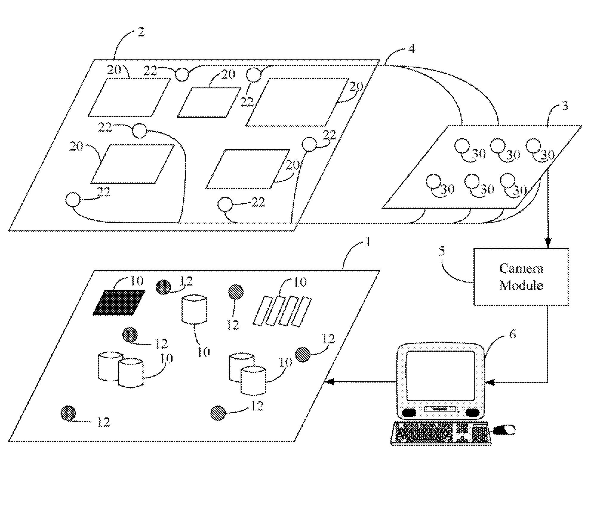
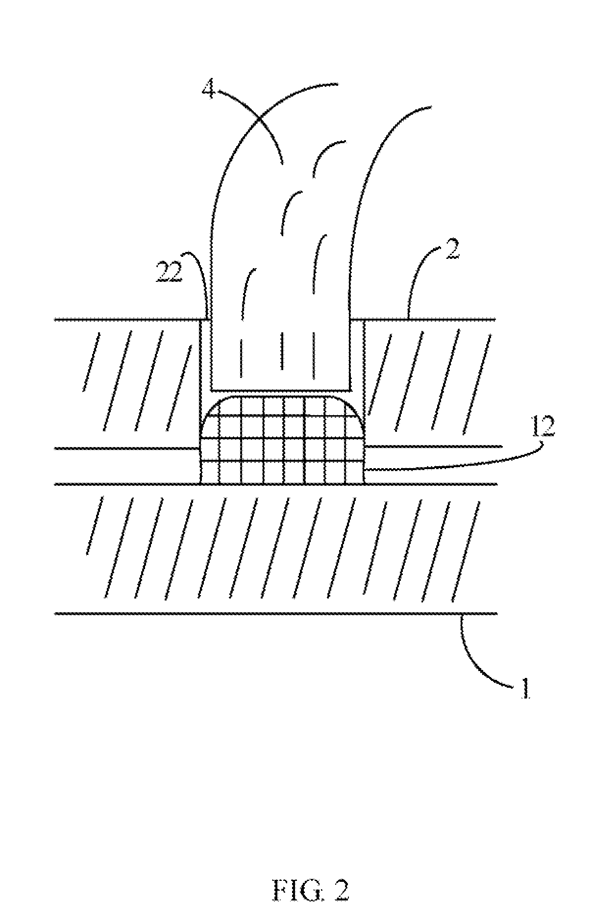
[0014]FIG. 1 is a schematic diagram of a system for testing light emitting diodes (LEDs) on a motherboard (hereinafter, “the system”) in accordance with one embodiment. The system typically includes: a motherboard 1, an insulating plate 2, a panel 3, a camera module 5 and a computer 6. The insulating plate 2 is positioned on the motherboard 1 and is overlaying with optical fibers 4. The optical fibers 4 in FIG. 1 are simply indicated and the real size of each of the optical fibers 4 is neglected. Actually, each of the optical fibers 4 is configured with a pipeline. The radius of each pipeline is approximately equal to or a little bit smaller than the radius of the LEDs. The insulating plate 2 is connected with the panel 3 via the optical fibers 4. In the preferred embodiment, the motherboard 1 can be incorporated into the computer 6. In an alternative embodiment, the motherboard 1 is external to the computer 6.

[0015]The motherboard 1 mainly includes multiple numbers of components 10...


PUM


Abstract

An exemplary method for testing light-emitting diodes (LEDs) on a motherboard is provided. The method includes: using a camera module to take a first bulb image of a corresponding number of transparent bulbs which are connected to each of the LEDs when the LEDs are set in a power-on state and taking a second bulb image of the transparent bulbs when the LEDs are set in a power-off state; processing the two bulb images and dividing each of the two bulb images into small pictures; calculating an average pixel value of each of the small pictures, calculating a first difference of each of the small pictures between the average pixel value and a first predetermined value, and calculating a second difference of each of the small pictures between the average pixel value and a second predetermined value; ascertaining a present state of each of the LEDs by comparing the two differences; obtaining test results by comparing the present state of the LEDs with the set state; and reporting the test results. A related system is also provided.

Description

BACKGROUND OF THE INVENTION[0001]1. Field of the Invention[0002]The present invention relates to the field of testing light emitting diodes (LEDs) and, particularly, to a system and method for testing LEDs on a motherboard.[0003]2. Description of Related Art[0004]Light emitting diodes (LEDs) have been applied with commercial products since the 1960s, due to their favorable characteristics. LEDs display high-shake endurance, long-service life, small power consumption and little heat production. As such, the LED can be applied for daily usage in a variety of ways, such as: household appliances, indicative illumination for equipments or as light sources. In recent years, a printed circuit board (PCB), such as a motherboard, has been made in such a way that it contains one or more LEDs. The one or more LEDs is / are used as external signals, internal diagnostics and for purposes of other suitable applications.[0005]In order to verify whether each LED located on the PCB works in a normal s...

Claims


Application Information

Patent Timeline
Patent Type & Authority Applications(United States)
IPC IPC(8): G06K9/00
CPCG06T7/001G01R31/2635G06T2207/30108
Inventor WU, KUAN-LINCHEN, WEI-YUAN
Owner HON HAI PRECISION IND CO LTD
Why Eureka
Try Eureka