

Interstage cooled turbine engine
a technology of turbine engines and cooling tubes, applied in the direction of liquid fuel engines, vessel construction, marine propulsion, etc., can solve the problems of rotor disks that are subject to both considerable centrifugal loads and heating
- Summary
- Abstract
- Description
- Claims
- Application Information
AI Technical Summary
Problems solved by technology
Method used
Image

Examples
Embodiment Construction
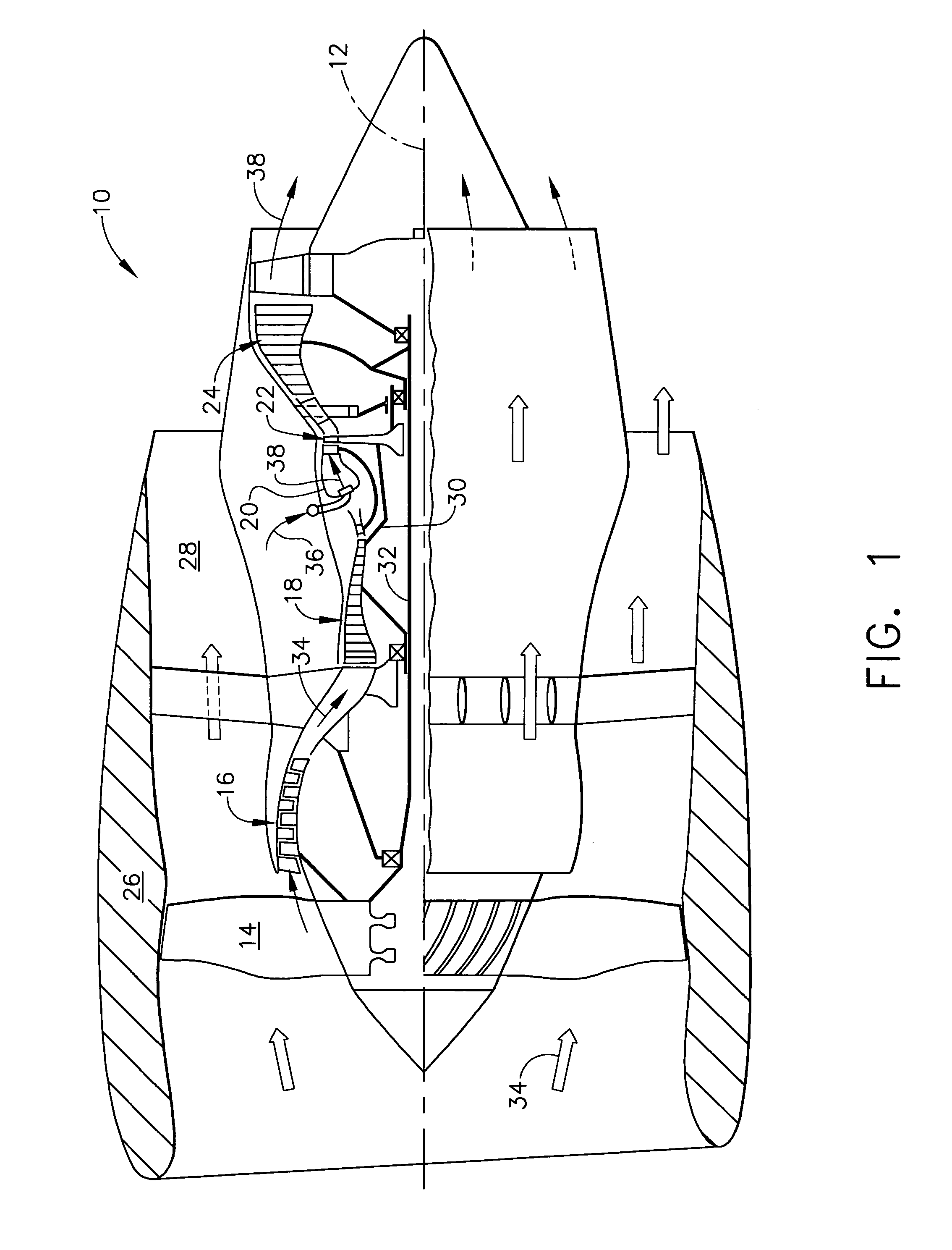
[0024]Illustrated schematically in FIG. 1 is an exemplary turbofan aircraft gas turbine engine 10. The engine is axisymmetrical about a longitudinal or axial centerline axis 12 and is suitably mounted to the wing or a fuselage of an aircraft (not shown) for powering an aircraft in flight in an exemplary application.
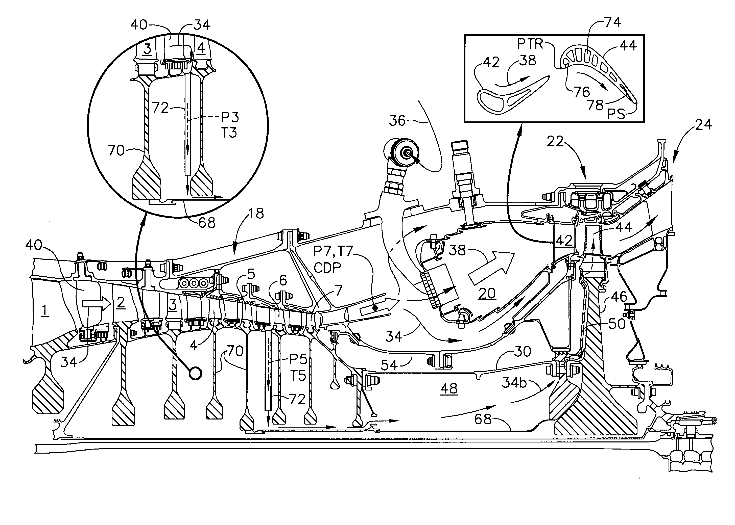
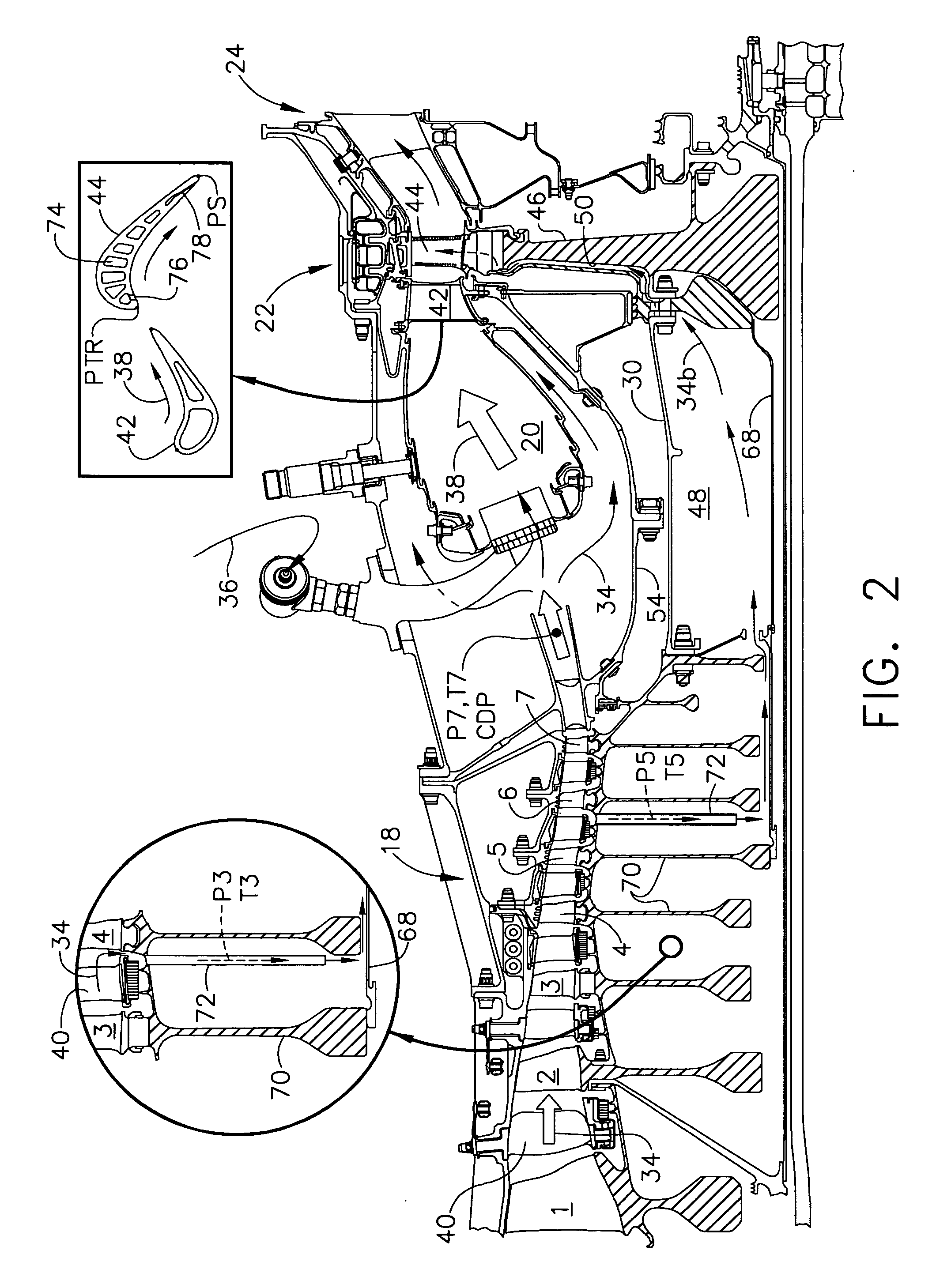
[0025]The engine includes in serial flow communication a fan 14, a low pressure or booster compressor 16, a high pressure (HP) compressor 18, an annular combustor 20, a high pressure turbine (HPT) 22, and a low pressure turbine (LPT) 24.
[0026]An annular nacelle 26 surrounds the fan 14 and defines an annular bypass duct 28 extending aft around the booster compressor 16. A first drive shaft 30 joins the HPT 22 to the HP compressor 18, and a second drive shaft 32 joins the LPT 24 to the fan 14 and booster compressor 16. The two drive shafts are suitably mounted in bearings in corresponding frames within the engine in a conventional configuration of the various engine compone...
PUM
 Abstract
Description
Claims
Application Information